
Blog
How to Create a Surface in Civil 3D (Step-by-Step)

How to Create a Surface in Civil 3D (Step-by-Step Guide for Surveyors and Civil Engineers)
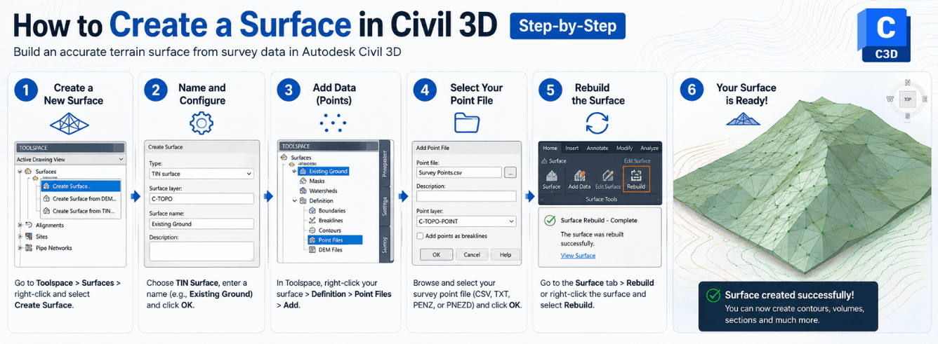
Knowing how to create a surface in Civil 3D is the single most important skill for any civil engineer or surveyor opening the software. Without a decent surface, nothing downstream works properly — your profiles miss existing ground, your corridor ties to nothing, and your volume calculations are guesswork.
- A TIN surface is the default and most versatile choice — start here unless you have a specific reason not to.
- You can build a surface from five main data sources: existing CAD points, imported survey data, DEM files, contours, or point cloud scans.
- Breaklines and boundaries are not optional extras — they keep triangulation from crossing kerbs, ridges, and site edges.
- Surface styles control what you see, not what the surface is. A surface can look like contours in one viewport and triangles in another.
- Genuine Civil 3D licences from Zoftis include full AutoCAD and start at $99/year — you need the real thing because cracked copies corrupt surfaces and break data references.
Why a good surface comes before everything else
Civil 3D is not just a drafting tool — it’s a dynamic model where everything connects. The surface is the base layer. Alignments reference it for existing ground profiles. Corridors target it. Grading objects tie to it. Cut-and-fill numbers pull straight from it.
A surface that triangulates badly because someone skipped breaklines will produce profiles with phantom dips and volume reports that are flat-out wrong. I’ve seen contractors chew through contingency budgets because the takeoff numbers came from a dirty surface. The time you spend getting the surface right at the start is never wasted.
Civil 3D surfaces do not store the source data inside themselves — they reference it. Move or delete the source points file, and your surface vanishes next time you open the drawing. Keep everything in one project folder structure.
TIN vs Grid vs Volume — which surface type to pick
When you open the Create Surface dialog box, Civil 3D offers a few types. Most engineers reach for the same one every time, but it helps to know what the others do.
| Surface type | Best for | Worth knowing |
|---|---|---|
| TIN surface | General land development, roads, grading | Triangulated Irregular Network — builds triangles between elevation points. The default and workhorse. Handles breaklines natively. |
| Grid surface | Large flat areas, DEM raster data | Evenly spaced grid rather than triangles. Faster on huge datasets but less precise along kerb lines and ridges. |
| TIN volume surface | Cut-and-fill calculations between two surfaces | Compares a base surface and a comparison surface, gives you a heat map of excavation vs fill. Essential for earthworks. |
| Grid volume surface | Grid-based volume comparison | Same idea as TIN volume, but gridded. Rarely used unless your data is already grid-based. |
| Corridor surface | Road and highway design | Auto-generated from corridor models. You don’t create these manually; the corridor builds them. |
For ninety percent of how to create a surface in Civil 3D tasks, you want a TIN surface. It gives the cleanest triangulation and plays nicely with every downstream feature. Stick with TIN unless you’ve got a specific reason to go grid.
Method 1: Building a surface from scratch with point groups
This is the classic workflow when you’ve got surveyed points sitting in your drawing, either as COGO points or blocks with elevation data. It gives you full control because you pick exactly which points feed the triangulation.
Step-by-step for creating a surface in Civil 3D from existing points
- Sort your points first. In the Prospector tab, right-click “Point Groups” and create a new group. Use the query builder to filter by description, raw code, or elevation range. Call it something like “EG_Survey_2025” so you remember what it is.
- Create the empty surface. Right-click “Surfaces” in Prospector, pick “Create Surface.” Set Type to “TIN surface.” Give it a meaningful name — “Existing_Ground” or “EG_Final” — and a description. Don’t skip the description; you’ll thank yourself in six months.
- Add point group data. Expand the new surface in Prospector, go to Definition → Point Groups, right-click, select “Add.” Pick your point group from the list. Civil 3D will triangulate instantly.
- Check triangulation. Change the surface style to one that shows triangles, and zoom in along key features — a ridge, a kerb line, a channel. Triangles shouldn’t cross obvious grade breaks.
- Add breaklines. Under Definition → Breaklines, add your breakline set. This forces triangulation edges to follow the breakline path instead of jumping across it.
- Apply a boundary. Under Definition → Boundaries, add an outer boundary to trim the surface to your site extent. Without this, Civil 3D may triangulate between distant points and create long sliver triangles that ruin accuracy.
If your surface doesn’t update after adding data, right-click it in Prospector and hit “Rebuild.” Civil 3D sometimes queues changes rather than applying them immediately.
Method 2: Creating a surface from a DEM file in under a minute
Digital Elevation Models come from government portals, drone surveys, and GIS data sources. A DEM import is the fastest way to build a large-area surface when you don’t have a point file — and it sidesteps the contour-throwing workflow that many engineers still reach for.
DEM import workflow
- In the Toolspace, switch to the Settings tab, right-click “Surface” under the drawing name, and pick “Create Surface.” Give it a name — “DEM_Regional” or similar.
- Go to the Insert tab on the ribbon, find the “Import” panel, and click “Import DEM.” Navigate to your .dem, .tif, or .asc file.
- Civil 3D will read the raster elevation data and generate a grid surface or TIN surface, depending on your choice in the import dialog. For most infrastructure work, pick TIN output.
- Once imported, immediately add a boundary to clip the surface to your project limits. DEM files often cover huge areas, and the full dataset will slow down the drawing.
- Check the surface statistics — right-click the surface, pick “Surface Properties,” go to the Statistics tab. Look at minimum and maximum elevation. If you see values that don’t make sense (elevations of -9999 or 32767), the DEM has no-data cells that need cleaning.
DEM import is ideal when you need regional context — siting a new road corridor, checking catchment boundaries, or doing feasibility studies where sub-metre precision isn’t required at the early stage. For detailed design, you’ll usually supplement the DEM with ground survey data.
DEM files don’t carry breaklines. If your site has kerbs, retaining walls, or channels, you must add those breaklines manually after import or the triangulation will smooth over features that shouldn’t be smooth.
Method 3: Turning contours into a surface (and when it’s a bad idea)
Contours are everywhere — legacy drawings, topographic maps, PDF underlays. The temptation to just chuck them into a surface is strong, but contour-to-surface conversion is the method that produces the most problems in practice.
When contour surfaces work
If your contours are true 3D polylines with real elevation data assigned, and they’re spaced close enough together, you can get a reasonable surface. Right-click the surface definition, pick “Contours,” select the polylines, and let Civil 3D build the triangulation.
When they fail
Flat triangles appear along contour lines. Why? Civil 3D triangulates between points along the same contour — which are all at the same elevation. The result is a stepped, unnatural surface with zero gradient along contour bands. Add breaklines derived from the contours themselves, and you can partially fix it, but you’re chasing your tail.
If someone hands you contours and says “make a surface,” your first question should be “do you have the original survey points or DEM?”
For creating a surface in Civil 3D from contours, the supplemental trick is to use the “Simplify Surface” command afterward to reduce the number of triangles, or to convert the contours to a point cloud and rebuild from those points. Either way, it’s a salvage job, not a best practice.
Method 4: Surface from point cloud and LiDAR data
LiDAR scans and drone photogrammetry datasets can contain millions of points. Civil 3D handles these through its point cloud tools, often with Autodesk ReCap Pro sitting in the middle to convert raw scan formats (LAS, E57, PTX) into RCP/RCS files that Civil 3D reads natively.
Point cloud to surface workflow
- Process in ReCap Pro first. Import your raw scan files, register scans if needed, clean out noise and non-ground points (cars, vegetation, buildings if you want bare earth). Export as an RCP project.
- Attach the point cloud in Civil 3D. Use the “Attach Point Cloud” command on the Insert tab. Once loaded, the point cloud appears as a dense coloured mass in model space.
- Create a surface from point cloud. On the Home tab, in the Create Ground Data panel, pick “Surface from Point Cloud.” Select the attached point cloud, and the dialog lets you filter by classification — critical because you can tell Civil 3D to only use points classified as “Ground,” skipping buildings and trees.
- Control density. Set a sampling distance. If your point cloud has points every 0.05 metres and you build a surface that dense, Civil 3D will grind to a halt. A 0.5m or 1m sampling is usually fine for earthworks design.
The point cloud surface workflow is increasingly the standard for brownfield sites, road resurfacing projects, and any job where a traditional survey crew would take weeks. The upfront processing time in ReCap Pro pays off in surface accuracy.
Breaklines and boundaries — the two things that stop your surface looking wrong
A raw triangulation doesn’t understand that a kerb exists. It’ll happily draw a triangle from a point at the road centreline straight across to a point on the footpath, cutting through the kerb face. The result is a surface that grades smoothly through a vertical edge that shouldn’t be smooth.
Breaklines in practice
Breaklines are 3D polylines, feature lines, or survey figures that tell the triangulation engine where to place triangle edges. Common breakline types:
- Standard breaklines — edges of pavement, kerb tops and toes, ridge lines, ditch centreline and top edges.
- Wall breaklines — where there’s a near-vertical face. Civil 3D handles these differently, allowing two points at different elevations but at the same X/Y position.
- Non-destructive breaklines — force triangulation edges without snapping existing triangle points. Useful when you don’t want to alter surface geometry elsewhere.
Boundaries
An outer boundary trims your surface to the project extents. Without one, Civil 3D triangulates the convex hull of all your points, which can create long, thin triangles across areas where no data exists. Those triangles generate false contours and mess up volume calculations.
You can also use a hide boundary to punch holes in a surface — useful for removing buildings, water bodies, or areas where survey coverage is poor. A show boundary does the reverse, re-exposing surface inside a larger hide.
Draw your breaklines on a dedicated layer and lock it. Nothing worse than accidentally stretching a kerb-line grip and not noticing until volume reports look weird weeks later.
Surface styles, labels, and volume calculation
Surface styles are purely visual. A single surface can display as contours in a plan viewport, as triangles in a working viewport, and as an elevation-banded heat map in a presentation sheet — all the same surface, different styles.
Setting up useful surface styles
Out of the box, Civil 3D ships with several surface styles under the Settings tab → Surface → Surface Styles. The ones you’ll actually use:
- Contours 1m and 5m — standard for plan presentation. Create your own with index contours at 5m and intermediate at 1m for UK work, or 2ft/10ft for US imperial.
- Triangles & Points — for QC. Shows exactly where your triangulation lines run and which source points they use.
- Elevation Banding — coloured bands by elevation range. Great for client presentations and cut/fill heat maps.
Surface labels
Spot elevation labels, contour labels, and slope labels all attach to surfaces. Before labelling, check your annotation scale — a contour label at 1:500 won’t be readable at 1:1250 without a different text height.
Volume calculations
Create a TIN volume surface with your existing ground as the base and proposed design as the comparison surface. The volume surface will report cut, fill, and net volumes in the statistics tab. For more detailed reporting, the Volumes Dashboard under the Analyze tab gives cut/fill by polygon, by station range, or by bounded area.
Volume surfaces don’t auto-update if the base or comparison surface changes. Rebuild the volume surface after any design tweak, or your takeoff numbers will be stale.
Four surface problems that eat hours and how to avoid them
1. The surface won’t build at all
Nine times out of ten, your points have zero elevation. Select a few points, check Properties. If the Z value reads 0.000, your survey import didn’t assign elevations correctly. Re-import with the correct point file format settings.
2. Surface looks “spiky” with random high or low triangles
You’ve got bad points — outliers in the survey data. Turn on triangles and points display style, zoom in on the spikes, and either delete the bad points or exclude them using a point group query with an elevation filter.
3. Flat spots along contour lines
As mentioned in the contour method section, this happens when triangulation uses multiple points at the same elevation. Swap your surface definition to point data instead, or add supplementary breaklines.
4. Surface slows the drawing to a crawl
Too many points. A LiDAR surface with a million points at 0.1m spacing is overkill for most civil design work. Use the “Simplify Surface” command or reduce point cloud sampling distance. A 1-metre grid is plenty for bulk earthworks; sub-0.5m is usually overkill unless you’re designing kerb tie-ins.
Need a genuine Civil 3D licence to put this into practice?
Autodesk Civil 3D for Windows — full AutoCAD included, for infrastructure and land development. From $99/year (50% off the standard $199). Delivered by email in 1–12 hours, activated on your own Autodesk account. 30-day money-back guarantee.
Get Civil 3D for $99/year →Also available: Civil 3D Commercial License — full commercial use rights, from $1,599
Frequently asked questions
What is the difference between a TIN surface and a grid surface in Civil 3D?
A TIN (Triangulated Irregular Network) surface builds triangles between irregularly spaced elevation points. It captures breaklines precisely and is the standard for engineering design. A grid surface uses evenly spaced elevation cells, which is faster on very large datasets but less accurate along grade breaks like kerb lines and ridges. For most civil engineering work — roads, drainage, site grading — TIN surfaces are the right choice.
Can I create a Civil 3D surface from a PDF or image of contours?
Not directly. You’d need to trace the contours as polylines and assign elevations manually, or use raster-to-vector conversion software first. Even then, the resulting surface will have flat-triangle problems. If at all possible, go back to the source and get the original DEM, point file, or survey data — the surface quality difference is substantial.
How do I add breaklines to a surface that already exists?
In the Prospector tab, expand your surface, go to Definition → Breaklines, right-click, and choose “Add.” Select your 3D polylines, feature lines, or survey figures. Set the breakline type (Standard, Proximity, Wall, or Non-destructive) and the mid-ordinate distance. The surface rebuilds automatically. Always zoom in along the breaklines afterward to verify the triangulation followed them correctly.
Why does my surface show flat triangles along contour lines?
This happens when you build a surface from contours. Civil 3D triangulates between points that sit on the same contour line — which are all at the same elevation. The result is flat, stepped areas. The fix is to either use source point data instead, or to generate breaklines from the contours and add them to the surface definition.
Can I use Civil 3D without a licence to practise creating surfaces?
Autodesk offers a free 30-day trial of Civil 3D from their website, which is perfect for practising surface creation workflows. For commercial project work, you need a genuine subscription. Unlicensed copies often have corrupted surface definitions that fail silently — triangulation looks correct but produces wrong volumes. A genuine Civil 3D licence from Zoftis starts at $99/year and activates on your own Autodesk account.