
Blog
AutoCAD for Architectural Drawing: Strengths, Limits and Setup

AutoCAD for Architectural Drawing: Strengths, Limits and Setup
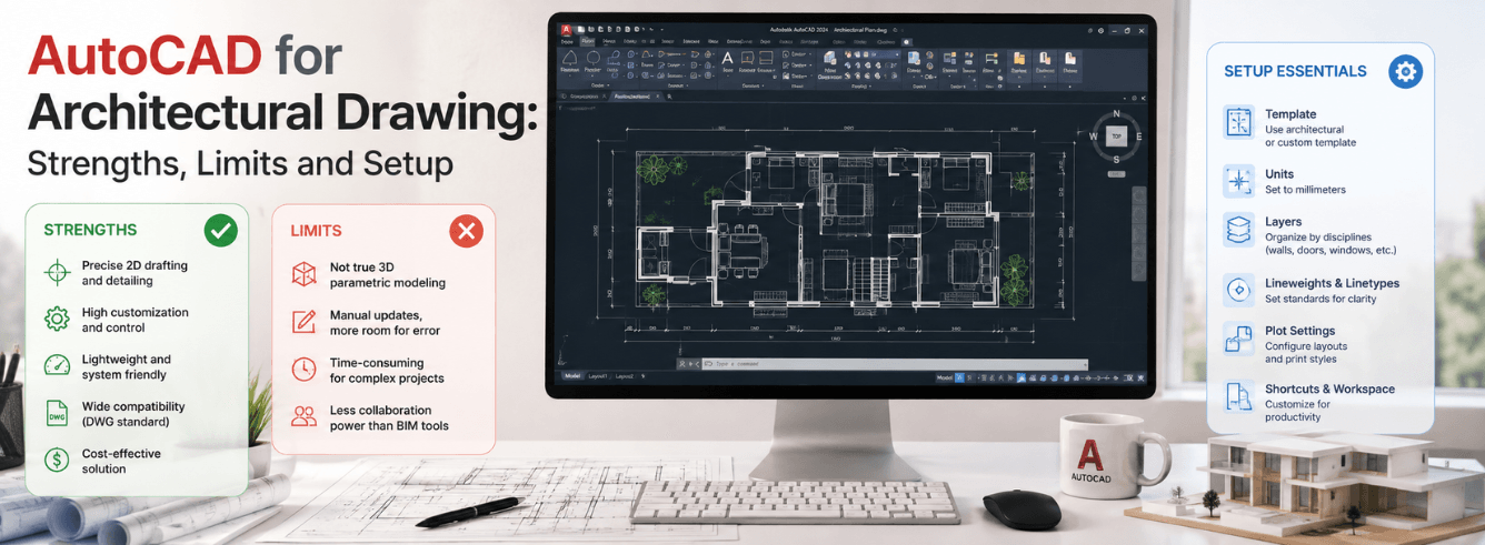
AutoCAD for architectural drawing remains the backbone of most architecture firms’ production workflows — not because it’s the newest tool, but because nothing else matches its precision, sheet-level control, and sheer reliability when construction documents need to go out the door.
- AutoCAD with the Architecture toolset gives you 8,500+ ready-to-use architectural components — walls, doors, windows, stairs — that generate sections and elevations automatically.
- The difference between AutoCAD and Revit architecture isn’t about “which is better” — it’s about whether your project needs BIM coordination or pure drafting control.
- A proper architectural setup (layer standards, annotation scales, title blocks, xrefs) must be built before line one is drawn — or the sheet set falls apart later.
- Genuine AutoCAD licences start at $59/year through Zoftis — substantially below Autodesk’s direct list price — with the same toolset access and commercial-use rights.
What AutoCAD actually does for architects
Walk through any architecture office and you’ll find AutoCAD for architectural drawing running somewhere. It might be on the detailer’s machine cranking out wall sections, on the interior designer’s screen laying out a reflected ceiling plan, or on the project architect’s second monitor with the master site plan loaded. The common thread: it’s producing the drawings that contractors actually build from.
AutoCAD’s architecture workflow centres on five deliverables that define most project sets:
- Floor plans — wall assemblies, door/window schedules, room tags, dimension strings, and referenced grid lines. Every architectural set starts here.
- Elevations — exterior and interior views with material callouts, height datums, and fenestration schedules. AutoCAD’s projection tools plus the Architecture toolset’s elevation generator speed this considerably.
- Sections — building cross-sections showing structural relationships, floor-to-floor heights, and envelope assemblies. The Architecture toolset can auto-generate these from a 3D model or you can draft them manually for total control.
- Construction documents — the full sheet set: cover sheet, code compliance, floor plans, RCPs, elevations, sections, wall sections, details, schedules, and specifications. This is where AutoCAD’s sheet layout and plotting precision become non-negotiable.
- Coordination drawings — base plans xref’d into structural, mechanical, electrical, and plumbing sheets. The xref workflow is the industry standard for multi-discipline coordination outside of BIM.
What separates architectural drafting in AutoCAD from generic CAD work is the layering, scaling, and annotation discipline. You don’t just draw lines — you build a structured file system that multiple consultants, the permitting authority, and the contractor all read the same way. That’s where the setup work below comes in.
The Architecture toolset — what’s included and why it matters
If your mental image of AutoCAD for architectural drawing is polylines and manual door swings from 2008, the Architecture toolset will surprise you. It ships with every current AutoCAD subscription (including the Windows licence available through Zoftis) and transforms the base drafting engine into an architecture-specific workspace.
Here’s what changes when you switch to the Architecture workspace:
| Feature | Base AutoCAD | With Architecture Toolset |
|---|---|---|
| Walls | Draw as parallel lines | Intelligent wall objects with styles, cleanup, and automatic intersections |
| Doors & windows | Manually draw and trim openings | Place from library; automatic opening generation in walls with dynamic sizing |
| Elevations & sections | Project manually from plans | Auto-generate from 3D building model; live update when plan changes |
| Stairs & railings | Calculate and draft manually | Parametric stair generator with code-compliant rise/run checking |
| Component library | None built in | 8,500+ architectural objects — furniture, fixtures, structural members, MEP symbols |
| Room documentation | Manual polyline boundaries | Room objects with automatic area calculation, finish schedules, and tags |
| Scheduling | Manual table creation | Live door, window, wall, and room finish schedules linked to the model |
The toolset saves time — Autodesk’s internal studies claim up to 60% productivity gain on architectural tasks versus base AutoCAD. But the real value is fewer coordination errors: change a wall type and the schedule updates; move a door and the opening in the elevation regenerates. It’s not full BIM, but it eliminates a lot of manual cross-checking.
The Architecture toolset is included with every AutoCAD subscription and AutoCAD LT subscription at no extra cost. The standalone “AutoCAD Architecture” product was discontinued — all its capabilities now live inside standard AutoCAD. If you buy through Zoftis, you get the same toolset access as someone paying Autodesk’s full list price.
AutoCAD vs Revit Architecture — picking the right horse
Every architecture firm faces the difference between AutoCAD and Revit architecture at some point — usually when a client or collaborator demands a BIM deliverable. The distinction isn’t subtle and choosing wrong mid-project creates genuine problems. Here’s the honest breakdown.
When AutoCAD for architectural drawing wins
- Projects where the deliverable is a permit set or construction document package — not a coordinated multi-discipline BIM model.
- Renovation and tenant improvement work — existing conditions rarely justify a full BIM build-out. AutoCAD handles as-built base plans, demolition sheets, and fit-out drawings with less overhead.
- Small to mid-size firms where project teams are 1–3 people and the coordination burden is manageable through xrefs and sheet set manager.
- Detail-intensive work — wall sections, flashing details, millwork shop drawings. AutoCAD’s line-level control still exceeds Revit’s for pure 2D detailing.
- Interior design and FF&E documentation — the furniture layout, finish plan, and RCP workflow in AutoCAD remains faster for many designers (more on this below).
When Revit Architecture takes over
- Projects requiring coordinated multi-discipline models — structural, MEP, and architecture all linking into one federated model.
- Large-scale new construction where a single change propagates across dozens of sheets and manual updating creates unacceptable risk.
- Clients demanding BIM deliverables — government projects, institutional work, and large developers increasingly require LOD 300+ BIM models at handover.
- Energy modeling and analysis — Revit’s model data feeds directly into energy simulation, daylight analysis, and life-cycle assessment tools.
- In-house multi-discipline teams where architects, structural engineers, and MEP engineers share a common platform.
AutoCAD is drafting that can do some modelling. Revit is a model that can do some drafting. The difference is which direction the data flows.
In practice, many firms run both. Schematic design and design development happen in Revit; construction documents — especially detailing, shop drawing review, and permit set production — often still finish in AutoCAD for architectural drawing control. You don’t have to pick one forever.
| Consideration | AutoCAD + Architecture Toolset | Revit |
|---|---|---|
| Learning curve | Weeks to productive; familiar drafting paradigm | Months to productive; requires BIM thinking shift |
| Project size sweet spot | Small–medium; tenant improvement; single-discipline | Medium–large; multi-discipline; complex coordination |
| 2D detail control | Complete line-by-line control | Good but constrained by model fidelity |
| Change coordination | Manual cross-checking required | Automatic propagation across all views |
| Annual licence cost (Zoftis) | $59/year (Windows) | $79/year (Windows) |
| Sheet set management | Mature Sheet Set Manager; battle-tested for CD sets | Sheets are views of the model; less flexible for mixed-source sets |
Using AutoCAD for interior design and fit-out drawings
Auto CAD for interior design is one of the most practical — and undersold — applications of the software. Interior designers and fit-out specialists need precision floor plans with furniture layouts, reflected ceiling plans with lighting coordination, finish schedules, and millwork elevations. The Architecture toolset plus some discipline-specific blocks handle this cleanly.
A typical interior design sheet set in AutoCAD
- Existing conditions / demolition plan — the as-built base showing what stays and what gets removed. Layer states control demo vs. new work visibility.
- Furniture and finishes plan — FF&E layout with finish codes, furniture tags, and material legends. Block libraries with dynamic attributes speed tagging.
- Reflected ceiling plan (RCP) — lighting layout, ceiling grid, soffit elevations, and switch-leg coordination with the electrical engineer.
- Interior elevations — reception desk, breakroom millwork, restroom tile patterns, feature wall details. The Architecture toolset’s elevation generator pulls these from the plan automatically.
- Finish schedule and door schedule — linked tables that update when finish codes or door types change. Not as automated as Revit’s schedules but fully controllable.
- Millwork and custom furniture details — this is where AutoCAD’s 2D drafting precision shines. Shop-drawing-level detail on cabinet construction, hardware specs, and material callouts.
Interior designers working in AutoCAD should build — or buy — a solid block library with dynamic attributes for furniture tags, finish codes, and equipment IDs. The time saved on a single tenant-improvement project pays for the setup effort ten times over. The Architecture toolset’s 8,500+ components give you a strong starting point.
The architectural drafting stack — layers, scales, and standards
Here’s the section neither competitor article includes — and the one that determines whether your drawing set looks professional or amateur. Architectural drafting in AutoCAD isn’t about knowing the commands. It’s about building a file structure that scales from schematic design through construction administration without collapsing under its own complexity.
Layer standards — pick one and enforce it
Layer standards aren’t optional once more than one person touches a drawing. The industry defaults are:
- AIA National CAD Standard (NCS) — dominant in US architecture. Layers follow the format
Discipline-Major-Minor(e.g.,A-WALL-FULL,A-DOOR-LEVL,I-FURN-OTLN). Most US consultants expect this structure. - ISO 13567 — international standard used across Europe and APAC regions. Agent-based naming with mandatory fields for agent, element, and presentation.
- Firm custom standard — almost every established firm has its own variation on NCS or ISO. The key isn’t which standard you pick — it’s that you document it and use layer states/filters to enforce it.
AutoCAD’s Layer Properties Manager and Layer States Manager let you save, export, and restore layer configurations. Build a template file (.dwt) with your layer standard pre-loaded and never start a project from a blank Layer 0 file.
Scale conventions that keep your drawings readable
Architectural scale in AutoCAD works differently than manual drafting. You draw everything at 1:1 in model space, then apply annotation scaling in paper space viewports. The scale you choose for a given drawing type matters because it dictates how much detail is visible — and what annotation sizes are readable.
| Drawing type | Common scale (Imperial) | Common scale (Metric) | What’s visible |
|---|---|---|---|
| Site plans | 1″ = 20′-0″ | 1:200 or 1:250 | Property lines, setbacks, building footprint, hardscape |
| Floor plans (overall) | 1/8″ = 1′-0″ | 1:100 | Room layouts, wall types, door swings, window locations |
| Floor plans (enlarged) | 1/4″ = 1′-0″ | 1:50 | Detailed dimensions, notes, finish codes, equipment tags |
| Building elevations | 1/8″ or 1/4″ = 1′-0″ | 1:100 or 1:50 | Material indications, height datums, window types |
| Building sections | 1/4″ = 1′-0″ | 1:50 | Structural relationships, envelope assembly, floor-to-floor |
| Wall sections | 3/4″ = 1′-0″ | 1:20 | Cladding attachment, waterproofing, insulation, flashing |
| Construction details | 1-1/2″ or 3″ = 1′-0″ | 1:10 or 1:5 | Full detail: fasteners, sealant joints, material thicknesses |
Title blocks — build once, use on every sheet
A proper title block isn’t a rectangle with text. It’s a block with attributes — project name, sheet number, sheet title, date, revision, drawn-by/checked-by stamps, and scale. Build one title block as a .dwg or .dwt file, xref it into each sheet, and use the Sheet Set Manager to push sheet-specific data into the attributes automatically. When the project name changes (and it will), you update it once — not on 40 individual sheets.
Annotation, hatch patterns, and making drawings readable
Annotation and hatch patterns separate a permit-ready architectural drawing from a CAD exercise. Both need setup before they work at scale.
Annotation that scales with your viewports
AutoCAD’s annotative scaling system lets a single dimension, text object, or multileader display at the correct size in multiple viewports with different scales. Turn on annotative properties for your text styles, dimension styles, and multileader styles — then add the scales your sheet set uses. An annotative dimension at 1/4″ = 1′-0″ and 1/8″ = 1′-0″ will adjust its plotted height automatically per viewport. Skip this setup and you’ll be creating duplicate annotation layers for every scale — the fastest path to an unmanageable file.
The most common architectural drafting mistake: setting annotation sizes based on what looks right on screen rather than what plots correctly at the intended scale. If your text prints at 0.06″ instead of the standard 3/32″ (0.09375″) minimum for permit drawings, the plans examiner may reject the set. Set your plotted text height in the style definition, not by eye.
Hatch patterns that communicate material
Hatch patterns in architectural drawings aren’t decorative — they’re a visual shorthand for material, assembly, and construction sequence. The conventions are well-established:
- ANSI31 (parallel lines) — generic section cut, steel, or concrete in section. Angle and spacing adjust for material type.
- AR-CONC (dot-and-triangle pattern) — concrete in section. The standard across US architectural drawings.
- AR-SAND (stipple pattern) — earth, gravel, or insulation depending on density. Adjust scale per the drawing.
- Custom plywood, batt insulation, and rigid insulation patterns — most firms have these in their template. Download or draw them once; use them project after project.
- Solid fill with screening — existing walls vs. new walls in renovation work. Plot with a screened color (e.g., color 8 or 9 at 50% screening) so existing conditions read as background.
Set hatch patterns to annotative scale or associate them with boundaries so they update when the enclosing polyline changes. Hatch that floats independent of its boundary is a coordination risk in every revision cycle.
XREFs, sheet layout, and plotting without surprises
The architectural sheet set is where the work either comes together or falls apart. External references (xrefs), paper space layout, and plotting settings determine whether the set looks clean — and whether it prints correctly at the permit office or print shop.
XREFs — the architectural coordination backbone
Architectural projects run on xrefs. The standard structure:
- Base plan — the master floor plan file containing walls, doors, windows, grids, and room tags. This gets xref’d into every discipline-specific sheet.
- RCP file — reflected ceiling plan with ceiling grid, lights, and overhead coordination. Xref’d into lighting and mechanical sheets.
- Consultant backgrounds — the structural engineer sends you their framing plan; you xref it under your architectural plan to check coordination. The MEP engineer xref’s your architectural base to align diffusers with your ceiling grid.
- Detail sheets — each construction detail is its own file, xref’d into the detail sheet layout. Change a flashing detail once; every sheet that references it updates.
Set XREF paths to relative, not absolute, before sharing files. An absolute path like C:\Projects\2026\ClientName\Base.dwg breaks the moment anyone else opens the file. A relative path (..\Base.dwg) survives folder moves and network changes. This single setting prevents more coordination calls than any other CAD discipline.
Sheet layout and plotting that works first time
Paper space layouts with properly configured page setups eliminate the “it looked fine on my screen” plotting disasters. The critical settings:
- CTB file (color-dependent plot style) — maps screen colors to plotted lineweights and screening. Your firm’s CTB is a design deliverable in its own right. A typical architectural CTB assigns thin lines (0.18mm) to dimensions and notes, medium lines (0.35mm) to wall outlines, and heavy lines (0.50mm+) to cut-plane elements in sections.
- Page setup per sheet size — ARCH D (24″×36″), ARCH E1 (30″×42″), ANSI D (22″×34″), and A1/A0 for metric projects. Set each once in your template, then never touch print settings again.
- PDF output with proper line merge — “Lines Overwrite” vs. “Lines Merge” setting in the PDF driver determines whether screened areas obscure linework underneath. Test this before bulk-plotting a 60-sheet set at 4 PM on deadline day.
- Sheet Set Manager — the single most underused architectural feature in AutoCAD. It organizes all sheets in a project, manages sheet numbering, publishes multi-sheet PDFs with one click, and pushes title block attributes to every sheet simultaneously. If you’re not using it, you’re doing sheet management the hard way.
What AutoCAD actually costs for architectural work
Autodesk’s direct pricing for an annual AutoCAD subscription — including the Architecture toolset — runs approximately $2,030/year for a commercial licence. That’s the list price for a single named-user seat with full access to all toolsets, cloud storage, and technical support. It’s a line item that adds up quickly for a small or mid-size architecture firm running three to five seats.
Through Zoftis, a genuine AutoCAD for Windows licence with the same Architecture toolset, same version access (2024–2026 releases), and same Autodesk account activation costs $59/year — roughly 97% below the direct list price. The licence is a single-user commercial subscription, delivered by email, activated on your own Autodesk account, and backed by a 30-day money-back guarantee.
| Licence option | Zoftis Price | Autodesk Direct (approx.) |
|---|---|---|
| AutoCAD for Windows (1 year) | $59 | ~$2,030 |
| AutoCAD for Mac (1 year) | $59 | ~$2,030 |
| AutoCAD LT for Windows (1 year) | $399 | ~$505 |
| Revit for Windows (1 year) | $79 | ~$2,910 |
Get genuine AutoCAD with the Architecture toolset
AutoCAD for Windows — 2024–2026 release, $59/year (reg $99), delivered in 1–12 hours with 30-day money-back guarantee. Same Autodesk account activation, same Architecture toolset, same commercial-use rights.
View AutoCAD for Windows →Also available: AutoCAD for Mac · Revit for Windows
Frequently asked questions
Do I need the full AutoCAD or is AutoCAD LT enough for architectural drafting?
For 2D architectural drafting — floor plans, elevations, construction documents — AutoCAD LT can handle most of the work. However, LT lacks the Architecture toolset (no intelligent walls, doors, or elevation generation), 3D capabilities, LISP routines, and some Sheet Set Manager automation. Most architecture firms run full AutoCAD because the toolset alone justifies the cost difference. If your work is pure 2D drafting for smaller residential or tenant-improvement projects, LT may suffice — but you’ll miss the productivity tools on larger sets.
Can I open and edit Revit files in AutoCAD?
No. Revit and AutoCAD use fundamentally different file formats (.rvt vs. .dwg). You can export Revit views to DWG format for coordination, and you can link DWG files into Revit as underlays, but the files aren’t natively compatible. If your consultants work in Revit and you work in AutoCAD for architectural drawing, establish a DWG export/import protocol at project kickoff to avoid format friction.
What layer standard should I use for architectural drawings?
In the United States, the AIA National CAD Standard (NCS) layer format is the safest choice — most architects, engineers, and permitting agencies recognize it. If your firm does international work, ISO 13567 is the equivalent. The important thing isn’t which standard you choose; it’s that every file in the project follows the same convention and that you document any firm-specific modifications. A documented, enforced layer standard prevents more RFIs than any single drafting convention.
Does the Zoftis AutoCAD licence include the Architecture toolset?
Yes. The AutoCAD subscription available through Zoftis is a genuine Autodesk licence that includes all seven specialized toolsets — Architecture, Mechanical, Electrical, MEP, Plant 3D, Map 3D, and Raster Design. The Architecture toolset activates through the AutoCAD workspace switcher once the software is installed and signed into your Autodesk account. No separate download or licence key is required.
Is AutoCAD still relevant now that BIM is standard on large projects?
Yes — and not just for legacy firms. AutoCAD for architectural drawing remains the standard for construction detailing, shop drawing coordination, permit-set production, and renovation projects where BIM’s overhead isn’t justified. Many firms that design in Revit still produce construction documents in AutoCAD for the sheet-level control it provides. The two tools coexist in most practices, and AutoCAD skills remain a baseline requirement for architectural job postings.
How do I set up annotative text and dimensions so they work at different scales?
Create an annotative text style (STYLE command, check “Annotative”), then set the paper text height to your desired plotted size — typically 3/32″ (0.09375″) for general notes and 1/8″ (0.125″) for titles. Create an annotative dimension style the same way. In model space, add the scales you need (1/4″ = 1′-0″, 1/8″ = 1′-0″, etc.) through the annotation scale control. Place text and dimensions using that style — AutoCAD automatically creates scale-specific representations that display at the correct size in each viewport.