
Blog
Fusion 360 CNC: From CAD Model to Machine Toolpaths

Fusion 360 CNC: From CAD Model to Machine Toolpaths
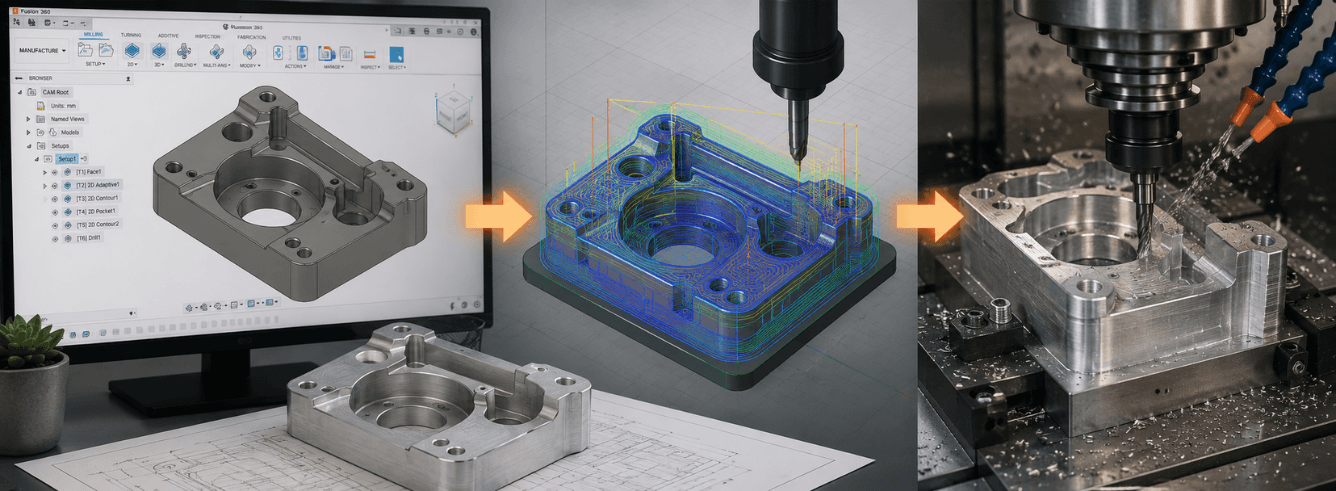
Fusion 360 CNC is an integrated manufacturing workflow that turns your 3D model into machine-ready G-code without ever leaving the same software environment.
- Fusion 360 CNC combines CAD and CAM — there’s no need to export, translate, or re-import geometry. Your model stays linked to your toolpaths.
- The tool library is your productivity backbone — building and organizing tools with feeds and speeds saves time on every job.
- Post-processors bridge the gap — selecting or customizing the right post means your G-code works with your specific machine controller.
- Simulation catches mistakes before metal moves — verify stock removal, avoid collisions, and confirm clearances.
Why integrated CAD/CAM matters for CNC
When you’re working toward a physical part, the connection between design and manufacturing shouldn’t feel like a handoff between two separate companies. Fusion 360 CNC brings CAD and CAM together in one package, and that changes how you approach your workflow.
Here’s the problem with separate CAD and CAM software: you design in one program, export a model file, import it into the CAM software, and then hope nothing breaks in translation. The model is no longer linked — if you change your design, you’re re-exporting and re-importing. It’s slow, error-prone, and creates friction you don’t need.
From design to machine in one environment
Fusion 360 CNC starts with the same model you designed. When you switch to the Manufacture workspace, your geometry is already there. There’s no import step, no translation, no missing surfaces or broken references.
This matters practically because:
- Design changes propagate — update a dimension in the CAD model, and the toolpaths can regenerate from the updated geometry without starting over.
- Your work coordinate system stays consistent — the same origin you used for design is the same one you’ll use for machining.
- The learning curve is shorter — you’re learning one interface instead of two completely different ones.
Who uses Fusion 360 CNC?
The Fusion 360 CNC workflow appears across industries — from MIT Fab Lab courses to Portland Community College manufacturing programs. It’s used by hobbyists with desktop machines, job shops with 3-axis mills, and manufacturers working with 5-axis setups. The common thread is needing to get parts made without spending weeks learning a dedicated CAM system.
The integrated workflow is a core buying reason for Fusion 360 over standalone CAD or CAM packages. When you compare cost and time saved, it’s a significant advantage.
Setup and stock definition — getting the foundation right
Every Fusion 360 CNC job starts with setup. This is where you tell the software what you’re cutting, where it’s located, and what machine you’re using. Get this wrong, and your toolpaths won’t align with your actual material.
Creating a setup
The setup defines your stock model and coordinate system. In the Manufacture workspace, you create a Setup operation that selects the model geometry, defines the stock size, and sets the work coordinate system (WCS).
Key decisions during setup:
- Stock — define the raw material shape and size. Use the “Fixed Stock” option if your stock is a known rectangular block. You can specify stock offsets from the model to account for rough material dimensions.
- Work coordinate system — set the origin and orientation. This origin should match how you’ll zero the machine. Typically, you choose a corner or the top center of the stock.
- Post-processor selection — choose a post-processor that matches your machine controller. This choice affects the G-code output format, but you can change it later.
Arranging parts on the stock
If you’re cutting multiple parts from a single sheet of material, the Arrange tool helps optimize placement to reduce waste. One practical guide notes that you should “make the bodies into components” before arranging, then use Modify > Arrange to position them on the stock.
You can define the stock size in the setup or use the Arrange tool with a specified bounding box. For sheet goods like plywood, you’d set the stock to match your material dimensions.
Workflow tip: When moving components for CAM layout, set the Move Object selection to “Components” rather than “Bodies.” If you use “Bodies,” you’ll move the original design geometry too.
Building a usable tool library
The tool library is where you define the cutting tools you’ll use. Fusion 360 CNC lets you build a library of tools with specific geometry, feeds, and speeds. Once you’ve set up your library, you can reuse it across jobs.
The tool library is more than a list of tools — it’s a database that stores critical information: tool diameter, flute count, cutting length, shank size, and material-specific feeds and speeds. A well-maintained library saves time on every new job.
Local vs cloud tool libraries
Fusion 360 offers two types of tool libraries: local and cloud. A local library stays on your machine, while a cloud library is shared across a team hub so multiple users can access the same tools.
Cloud libraries are ideal for shops with multiple CAM programmers or designers. They ensure everyone uses the same tool definitions, reducing variation and errors. To enable cloud libraries, go to Preferences > General > Manufacture and check “Enable Cloud Libraries.”
Importing and editing tool libraries
Fusion supports importing tool libraries in JSON or TOOLS format. You can also import libraries from tool manufacturers if they provide compatible files. The tool library manager lets you add new tools, edit existing ones, and organize libraries by type.
For bulk edits, Fusion can export tool libraries as CSV files. This allows you to edit tool parameters and add your own tools in Excel, then import the updated library back into Fusion. This is useful for renaming tools, updating speeds, or copying rows to create new tools with similar properties.
What to define in the tool library
Each tool entry should include:
- Tool geometry — diameter, corner radius, flute length, overall length, shank diameter
- Feeds and speeds — spindle speed (RPM), cutting feedrate, plunge feedrate, ramp feedrate
- Tool number — matches the tool number in your machine’s tool changer
- Material-specific data — you can define different feeds and speeds for different materials
The tool library is often overlooked, but it’s one of the biggest time-savers in Fusion 360 CNC. A good library means you’re not re-entering tool data for every job.
Toolpath strategies — from roughing to finishing
Fusion 360 CNC offers a range of toolpath strategies. The strategy you choose depends on what you’re cutting and what you want the result to look like. Most jobs use a combination: roughing to remove bulk material, then finishing to hit the final dimensions.
2D operations for simple parts
The 2D toolpaths are the workhorses of Fusion 360 CNC for sheet goods and prismatic parts:
- 2D Contour — cuts along the outline of a feature. Used for profiling parts, cutting pockets, and creating slots.
- Face — removes material from the top surface of the stock. Used to flatten stock or create a clean reference surface.
- Drill — creates holes using a drilling cycle. Available cycle types include peck drilling, deep drilling with full retract, and chip breaking.
- Adaptive Clearing — a roughing strategy that maintains a constant load on the tool. It uses a trochoidal toolpath pattern that’s more efficient than traditional pocketing and extends tool life.
For a CNC router project, the typical workflow is: face the top surface, then use 2D contour with specified tool diameters for different cuts, and finally drill the mounting holes. For the drill operation, selecting the “Deep Drilling – Full Retract” cycle helps clear chips and keep the tool from clogging when drilling deep holes.
3D operations for complex surfaces
For contoured surfaces, Fusion 360 CNC offers 3D toolpaths:
- Parallel — cuts parallel to a specified plane or surface.
- Scallop — maintains a consistent stepover across complex surfaces.
- Morph — follows the shape of the selected surfaces.
- 3D Contour — finishes edges and boundaries in 3D.
The 3D toolpaths are where Fusion 360 CNC’s integrated workflow really shines. You design the complex surface in the same environment where you generate the toolpath, so there’s no surface translation or healing step.
Multiple depths and stepover
For most roughing operations, you’ll use Multiple Depths to take cuts in layers. The maximum roughing depth is defined as the axial depth of cut per pass. For finishing, you care about stepover (the distance between adjacent toolpath passes).
A practical guide describes adjusting “Optimal Load” in adaptive clearing to control the tool engagement — lowering this value reduces stress on the CNC and the endmill.
Dogbone fillets for assembly
When designing parts that fit together (like tab-and-slot joints), you need to account for the fact that a round tool can’t cut a sharp internal corner. The dogbone fillet adds a small round relief at the corner of a slot so that square tabs fit properly.
Fusion 360 has a dogbone add-in or you can manually create the fillets. Without dogbone fillets, press-fitting can be difficult and require extra force.
Simulation and verification — cut virtual chips first
Simulation is the safety net of Fusion 360 CNC. It shows you exactly what the machine will do before you start cutting real material. The simulation verifies stock removal, checks for collisions, and lets you spot clearance issues.
Running a simulation
Once you’ve generated toolpaths, right-click the setup folder and select Simulate. The simulation shows the stock being cut away. You can control the simulation speed, view from different angles, and inspect the final result.
Simulation reveals several potential issues:
- Stock remaining — does the simulation remove all the material you expect?
- Clearance — does the tool move safely above clamps and fixtures?
- Collisions — does the tool holder or collet hit the workpiece or fixtures?
- Toolpath order — are operations in the right sequence (roughing before finishing)?
Using simulation for process optimization
Simulation isn’t just for error checking. It also helps optimize your machining process. By watching the simulation, you can see if toolpaths are efficient or if there’s excessive air-cutting (the tool moving without cutting material).
In one Autodesk University case study on manufacturing a motorsport component, the presenter used simulation to validate a complex part before machining. The project required programming and machining a rotor hat, taking 95 minutes to program and 145 minutes to machine.
Pro tip: Run the simulation with the toolpath display turned on. Watch the tool movement to ensure your clearance and retract heights are set properly.
Post-processors — the final translation
A post-processor is a specialized software tool that converts CAD/CAM data into a format that CNC machines can understand. It acts as the bridge between your toolpaths and your specific machine controller.
Without the right post-processor, your G-code won’t work on your machine. The post handles the specific syntax and formatting your controller expects — things like how it handles tool changes, coolant commands, and rapid moves.
Finding and selecting a post-processor
Fusion 360 includes an online library of post-processors for hundreds of machine and controller combinations. You can find posts for machines from Haas, Mazak, Trumpf, and many others.
To select a post-processor:
- In the Manufacture workspace, right-click your setup or NC program and select Post Process.
- Choose a post-processor from the list — either from the Fusion library or from your personal library.
- You can filter by machine type, controller, or manufacturer.
The post-processor library includes support for laser, plasma, waterjet, and milling machines. Common posts include Haas, Fanuc, Mach3, GRBL, UCCNC, and many more.
Customizing a post-processor
Sometimes you need to modify a post to work with your specific setup — adding a fourth axis, changing the file extension, or adjusting the startup sequence. Post-processors in Fusion are JavaScript files with a .cps extension.
Common customizations include:
- Adding a 4th axis — enable the A, B, or C axis by editing the machine configuration section.
- Changing output format — file extensions, line numbering, or using G1 instead of G0 for certain moves.
- Adjusting tool change commands — the sequence of commands when the machine switches tools.
For editing, Autodesk recommends using Visual Studio Code with the Fusion 360 Post Processor Utility extension. This provides syntax highlighting and makes it easier to find variables and functions.
Important: If you’re using the Fusion 360 for Personal Use license, be aware of its limitations. Some post-processor modifications may be restricted, and the license changes all G0 moves to G1 commands, which can affect toolpath behavior.
Fusion 360 CNC compared to standalone CAM
If you’re deciding between Fusion 360 CNC and a standalone CAM package, the choice comes down to workflow and cost. Here’s how it stacks up.
| Factor | Fusion 360 CNC | Standalone CAM |
|---|---|---|
| CAD integration | Full integration — design and CAM in one environment | Requires import — model translation and potential geometry issues |
| Workflow efficiency | Design changes update toolpaths automatically | Design changes require re-importing the model and re-creating toolpaths |
| Cost | Subscription includes CAD, CAM, CAE, and PCB tools | Separate purchase or subscription for CAM, plus CAD software |
| Post-processor library | Extensive built-in library plus customization tools | Varies — some packages have limited posts or charge for custom posts |
| Learning curve | One interface for design and manufacturing | Two interfaces to learn — CAD and CAM |
| Collaboration | Cloud-based with tool libraries and design sharing | Often file-based, harder to collaborate across teams |
The integrated workflow is the defining advantage of Fusion 360 CNC. If you’re designing parts and manufacturing them in-house, the time saved on translations and updates adds up quickly. For job shops and product development teams, this integration is a competitive advantage.
Frequently asked questions
What is the basic Fusion 360 CNC workflow?
The basic workflow is: design your model in the Design workspace, switch to the Manufacture workspace, set up your stock and coordinate system, select a post-processor, generate toolpaths, simulate the cuts, and post-process the G-code. The integrated CAD/CAM environment keeps your model linked to your toolpaths throughout.
How do I set up a tool library in Fusion 360?
You can build a tool library in the Tool Library manager under the Manage tab in the Manufacture workspace. Add tools with specific geometry, feeds, and speeds. You can use local libraries or cloud libraries for team sharing. Export as CSV for bulk edits in Excel.
What’s the difference between 2D and 3D toolpaths?
2D toolpaths (like 2D Contour, Face, and Drill) work with flat geometry and are used for sheet goods, pockets, holes, and profiles. 3D toolpaths (like Parallel, Scallop, and Morph) work with contoured surfaces and are used for complex shapes and 3D machining.
How do I choose a post-processor for my CNC machine?
Select a post-processor that matches your machine controller and machine type. Fusion has a built-in library with posts for Haas, Fanuc, Mach3, GRBL, UCCNC, and many others. You can also customize existing posts or use the Post Services Marketplace for paid custom posts.
Can I use Fusion 360 CNC for 4th and 5th axis machining?
Yes, Fusion supports multi-axis machining. Many post-processors in the library already support 4 and 5-axis code, though these axes may be disabled by default and need to be enabled through post properties or by editing the post file.
Ready to get started with Fusion 360?
Genuine Autodesk Fusion 360 for Windows — CAD, CAM, CAE and PCB included. From $59/year. Delivered by email, activated on your own Autodesk account within 1–12 hours. 30-day money-back guarantee.
Get Fusion 360 Now →Also available: Fusion 360 for Mac (native Apple Silicon) and Fusion 360 Commercial License