
Blog
How to Set the Coordinate System in Civil 3D Correctly

How to Set the Coordinate System in Civil 3D Correctly
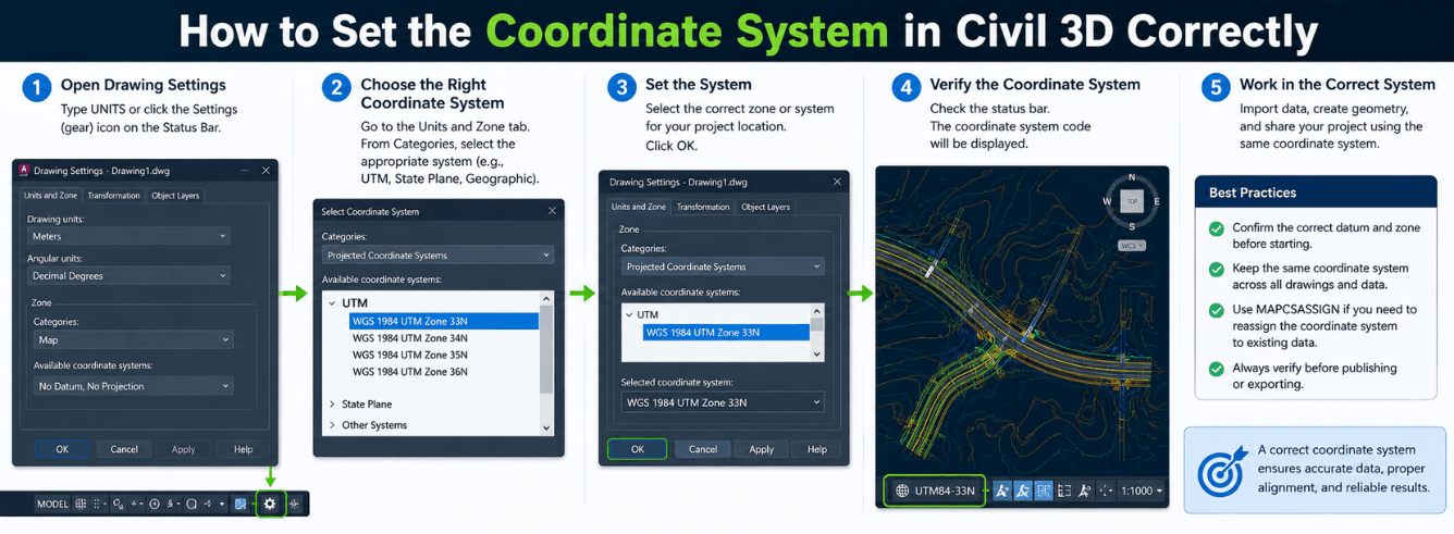
If you need to set the coordinate system in Civil 3D correctly — and do it before your surfaces, alignments, and pipe networks drift out of alignment with the real world — you’re in the right place. Every single object you draw lives on a coordinate grid, whether you’ve defined that grid or not. The moment you skip this step, you’re gambling with your project’s accuracy.
- A drawing always has coordinates — setting the system explicitly prevents drift, misalignment, and data-exchange failures.
- Two separate places in Civil 3D store coordinate information: Drawing Settings (the spatial reference) and Geolocation (the live-map pin).
- Transforming existing drawings requires different workflows for AutoCAD objects vs. Civil 3D objects — you can’t mix them in one operation.
- Grid-to-ground projects need an extra transformation step; skipping it can throw your site by several feet.
- An incorrect coordinate system is fixable — but verifying the result with a known control point is non-negotiable.
Why the coordinate system matters in Civil 3D
Every point, line, surface vertex, and alignment PI you place in Civil 3D sits on a specific X, Y, and Z value. You don’t get a choice about that — the software assigns coordinates the moment you click. The question is whether those numbers mean something in the real world or just float in arbitrary model space.
When a coordinate system is assigned, Civil 3D knows how to relate your flat drawing grid to a curved-earth datum, a specific projection, and a defined zone. That unlocks three things civil engineers and surveyors depend on daily.
What georeferencing actually gives you
- Accurate data exchange. A surface exported from your drawing lands exactly where a GIS analyst or drone processor expects it. Without georeferencing, your exported SDF or LandXML can float kilometres off-target.
- Coordinate-aware labels. Station-offset labels, Northing/Easting tables, and spot elevations all reference the correct projection — so a contractor in the field staking from your sheet doesn’t end up one property over.
- InfraWorks and BIM 360 interoperability. Autodesk’s cloud collaboration tools need a defined coordinate system to position your model relative to other discipline models. No system? No correct placement.
Even if you never assigned a coordinate system, your drawing still has one — Civil 3D defaults to an arbitrary local grid. The software won’t warn you. It’ll just let you build a kilometre-long corridor in coordinate limbo.
Where Civil 3D stores coordinate system information
This trips up even experienced users. Civil 3D actually keeps coordinate system data in two separate places, and they don’t automatically talk to each other.
Drawing Settings — the spatial reference engine
This is the real one. When you open Toolspace → Settings tab → right-click the drawing name → Edit Drawing Settings, the Units and Zone tab controls the EPSG code, datum, projection, and coordinate zone for everything in that DWG. Civil 3D objects — surfaces, alignments, pipe networks, pressure networks, corridors, cogo points — all read from this setting. If you export to LandXML, SDF, or IFC, this is the metadata that travels with the geometry.
Geolocation — the live-map pin
The Geolocation tab (or the GEOGRAPHICLOCATION command) sets where your drawing sits on the online Bing map. It’s useful for snapping a site aerial under your linework, but it doesn’t drive object georeferencing the way Drawing Settings do. You can set a different coordinate system here by accident and Civil 3D won’t object — it’ll just show your corridor floating in the ocean on the map while your labels read a perfectly sensible state plane coordinate.
We’ve seen project teams set the Geolocation and assume the drawing is fully georeferenced. It isn’t. Always check Drawing Settings first — that’s the source of truth for spatial metadata.
How to set the coordinate system in Civil 3D, step by step
The core workflow to set the coordinate system in Civil 3D takes under two minutes. Here’s the exact sequence, whether you’re starting a fresh drawing or fixing one that was never assigned.
Method 1: Drawing Settings (recommended, always do this)
- Open Toolspace. If it isn’t visible, type
TOOLSPACEand press Enter. - Switch to the Settings tab.
- Right-click the drawing name at the very top of the tree — it’s the filename with the Civil 3D icon.
- Select Edit Drawing Settings.
- Go to the Units and Zone tab.
- Under “Categories,” pick your region. For US projects, you’ll typically drill into USA, State Plane or USA, UTM. For international work, scroll through the country list or type a known EPSG code into the search.
- Select the exact zone — NAD83 Texas State Planes, South Central Zone (US Survey Foot), as an example.
- Check the datum and units. Civil 3D defaults to International Foot for many state plane zones; if your survey uses US Survey Foot, change it now.
- Click OK.
That’s it. Every Civil 3D object you create from that point forward inherits this spatial reference. Existing objects already in the drawing do not get retroactively tagged — they keep the coordinate system that was active when they were created. To transform them, jump to the transformation section below.
Method 2: Assigning via the Geolocation tab
Type GEOGRAPHICLOCATION or switch to the Geolocation ribbon tab and click Set Location. Choose “From Map” to pick a point interactively on Bing Maps, or “From File” to import a KML/KMZ or geo-referenced image. When you pick a location, Civil 3D prompts you to select a coordinate system — and whatever you pick here also populates the Drawing Settings. This route is fine for initial setup, but always verify by opening Drawing Settings afterward and confirming the zone and units match your project spec.
Typing an EPSG code directly into the search bar inside the coordinate system picker is the fastest way to land on the right zone — no scrolling through twelve nested categories. If your surveyor hands you “EPSG: 26914,” just type it.
Choosing the right coordinate zone: State Plane, UTM, or custom
Civil 3D ships with thousands of predefined coordinate systems, but for most civil projects in North America, the decision boils down to two families. Getting the zone wrong by even one county can shift your entire site.
| Decision factor | State Plane Coordinate System (SPCS) | Universal Transverse Mercator (UTM) |
|---|---|---|
| Typical scale factor distortion | ~1 part in 10,000 (designed to minimise distortion within each narrow zone) | ~1 part in 2,500 (wider zones = more scale variation at edges) |
| Zone width | Usually county-sized or smaller | 6 degrees of longitude wide |
| Most common in | US state and local government projects; most DOT plan sets | Federal projects, regional mapping, international work |
| Unit convention | US Survey Foot (check — NAD83 zones may also offer International Foot or Meter variants) | Always meters |
| Grid-to-ground scale factor needed? | Often — especially for site-scale civil design where 0.9999 distortion still matters | Almost always — UTM distortion at zone edges can exceed 1:2,500 |
What to ask the surveyor before you pick
If you’re inheriting a project, don’t guess. Ask the surveyor or project manager three specific questions:
- “What coordinate system and datum is the control network in?” — Not “what do you think it’s in.” Get the EPSG code or the exact Autodesk category string.
- “Is the delivered surface on grid or ground?” — This changes whether you apply a transformation or a scale factor.
- “What linear unit — US Survey Foot or International Foot?” — Mixing these across a half-mile site can introduce a quarter-inch of error. On a ten-mile corridor, it’s inches.
A wrong zone selection is the single most expensive coordinate mistake in civil design — and it’s fully preventable with one phone call.
Grid-to-ground: when your coordinate system needs a transformation
Every projected coordinate system — State Plane, UTM, or otherwise — introduces some distortion because you’re flattening a curved earth onto a flat plane. For regional mapping, a 1:10,000 scale factor is negligible. For a 40-acre site where the contractor is staking building corners, it isn’t.
Grid-to-ground correction bridges that gap. You apply a combined scale factor (CSF) — typically calculated from the project’s average elevation and its position within the projection zone — to scale grid distances down (or up) to ground distances. Civil 3D handles this through the Transformation tab inside Drawing Settings.
Applying a combined scale factor in Drawing Settings
- Open Drawing Settings → Transformation tab.
- Enable “Apply transform settings.”
- Enter the combined scale factor your surveyor provides. A typical CSF for a state plane zone project at moderate elevation might be 0.9999-something.
- Set a reference point (often a project base point) around which the scaling is applied.
- Click OK. Civil 3D now reports ground distances in labels while storing grid coordinates internally.
Grid-to-ground transformations only affect Civil 3D labels and reports. The underlying coordinate values in the drawing database remain on grid. If you export to a system that doesn’t read the Civil 3D transformation metadata, the receiving software will see grid values — not ground. Communicate this clearly to your GIS and survey stakeholders.
Transforming an existing drawing to a new coordinate system
Sometimes you don’t get to set the coordinate system correctly from the start. The project arrives mid-stream, the survey control was revised, or an agency changed the delivery zone. Now you need to move everything — and the method depends entirely on what kind of objects live in your DWG.
Civil 3D offers two distinct transformation paths, and they do not overlap. Use the wrong one, and half your objects won’t move.
The Old Way: transforming AutoCAD objects (lines, blocks, text, polylines)
This method uses the Map 3D query engine built into every Civil 3D seat. It works on plain AutoCAD geometry only.
- Open your existing DWG and assign its current coordinate system via Drawing Settings. Save and close.
- Open a brand-new DWG. Assign the target coordinate system you want to move to — also via Drawing Settings.
- Type
MAPWSPACEand set it to On to open the Map Task Pane. - Switch to the Map Explorer tab, right-click Drawings, and select Attach. Browse to the original DWG, add it, and click OK.
- In the Map Explorer tree, right-click the attached drawing and choose Activate if its icon is greyed out.
- Under Query Library, right-click Current Query → Define.
- Click Location → All → OK. Check the Draw option, then click Execute Query.
- Zoom Extents. Your AutoCAD objects now sit at the transformed coordinates in the new zone. Right-click the attached drawing → Detach, then save.
If the Attach dialog doesn’t appear, the Map support file search path is missing. Go to Options → Files → Support File Search Path and add C:\Program Files\Autodesk\AutoCAD [version]\Map\Support\en-us. Restart Civil 3D and the dialog will appear.
The New Way: transforming Civil 3D objects (surfaces, alignments, pipe networks)
This uses the dedicated transformation tool inside Toolbox and works on Civil 3D-native objects only.
- Ensure the drawing’s current coordinate system is set correctly in Drawing Settings.
- Go to Toolbox on the Toolspace panel → Miscellaneous Utilities → Drawing Transformations → Coordinate System Transformation.
- If the tool is greyed out, you may need to install it through the Autodesk Account Manage Portal — it’s a free extension that ships with your subscription.
- In the dialog, select the destination coordinate system and click OK.
- Civil 3D transforms every Civil object and generates a report listing what moved, by how much.
Never mix AutoCAD and Civil 3D objects in a single transformation run. Separate them into two DWGs, transform each with the correct method, then XREF or paste them back together.
Common coordinate system mistakes and how to catch them
Even careful teams make these. We’ve seen every one of them in real project files — and they’re all diagnosable before they reach a construction stakeout.
The mistakes, ranked by how often they show up
- No coordinate system assigned at all. The drawing opens, everything looks fine, but nothing exports correctly. Fix: open Drawing Settings — if the zone field is blank, it was never set.
- Wrong zone selected (adjacent state plane zone). A project near a county line gets zoned to the neighbouring county’s SPCS. Coordinates look plausible but shift everything by miles. Fix: spot-check a known control point’s Northing/Easting against the surveyor’s plat.
- Units mismatch (US Survey Foot vs. International Foot). NAD83 zones in Civil 3D often default to International Foot. If your survey crew worked in US Survey Foot, every coordinate is off by roughly 2 parts per million — small per point, cumulative over a corridor.
- Datum confusion (NAD83 vs. NAD83 (2011) vs. WGS84). These are close but not identical. Loading a WGS84 drone surface into a NAD83 state plane drawing without a datum transformation can throw vertical by a metre or more.
- Geolocation set but Drawing Settings left blank. The Bing map shows the right location, so everyone assumes the file is georeferenced. It isn’t — exports will fail or float.
Quick diagnostic: does your drawing pass these three checks?
- Open Drawing Settings → Units and Zone. Is a zone selected? If yes, does its name match what the surveyor specified?
- Type
GEOGRAPHICLOCATION→ check the coordinate system listed. Does it match what Drawing Settings says? - Place a cogo point at a known control coordinate. Does the Northing/Easting label match the surveyor’s control sheet to the decimal?
If all three pass, your coordinate system is set correctly. If any one fails, stop and fix it before sending files out.
Working in Civil 3D? Get a genuine licence without the full Autodesk-direct price.
Civil 3D for Windows — full AutoCAD included, for infrastructure and land development. From $99/year (regularly $199), redeemed to your own Autodesk account, delivered by email within 1–12 hours, backed by a 30-day money-back guarantee.
Get Civil 3D — $99/yearAlso available: Civil 3D Commercial License — $1,599 (save 39%)
Frequently asked questions
How do I know what coordinate system my surveyor used?
Ask directly for the EPSG code or the full Autodesk coordinate system string (e.g., “NAD83 Texas State Planes, South Central Zone, US Survey Foot”). If they only provide a zone name and datum, cross-check it in Civil 3D’s coordinate system picker — same name can mean different things across different datums. The surveyor’s control sheet should also list at least one known Northing/Easting pair you can use to verify your drawing after assignment.
Can I set the coordinate system after I’ve already started designing?
Yes — assign the correct system through Drawing Settings immediately. Existing objects will keep their current coordinate values, which is fine if they were drawn on the correct grid to begin with. If the objects were drawn in a different coordinate system, you’ll need to run a transformation (see the transformation section above). The longer you wait, the more objects you’ll have to transform later.
What’s the difference between assigning a coordinate system and georeferencing an image?
Assigning a coordinate system (Drawing Settings) tells Civil 3D what spatial reference to use for all geometry and exports. Georeferencing an image (via MAPIINSERT or the Geolocation tab) places a raster or aerial onto that coordinate grid by defining its insertion point, rotation, and scale. You can georeference an image without assigning a coordinate system, but exports and data-sharing will still fail because the drawing itself has no spatial metadata.
Will setting a coordinate system automatically move my objects to the right place?
No. Simply setting a coordinate system through Drawing Settings does not move anything — it only assigns metadata. If your objects are already on the correct coordinates for that zone, you’re done. If they’re on the wrong coordinates (e.g., they were drawn in UTM but you just assigned a State Plane system), you need to run a transformation using either the Map Query method or the Toolbox transformation tool.
How do I handle a project that spans two coordinate zones?
Pick one zone as the project’s primary system and assign it to the master drawing. For data that originates in the adjacent zone, transform it into the primary zone before bringing it in. Some teams keep separate base files per zone and XREF them together for sheet production, using Civil 3D’s coordinate transformation on the XREF. For long linear corridors (pipelines, highways), UTM may be more practical than State Plane because its wider zones reduce the number of zone-boundary crossings.