
Blog
AutoCAD Scale Factor Explained (With a Conversion Chart)

AutoCAD Scale Factor Explained: A Zero-Confusion Workflow Guide
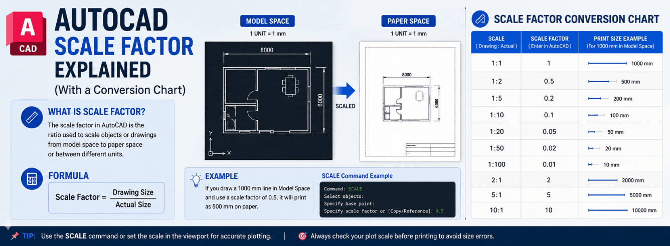
Every AutoCAD user eventually hits the same wall: you’ve drawn a perfectly detailed floor plan, but when it’s time to plot, the text is either microscopic or comically huge. Mastering the autocad scale factor is the single skill that turns your model space chaos into a crisp, professional sheet set.
The real problem scale factors solve
New users often think the problem is shrinking the building to fit on paper. That’s a viewport’s job. The actual problem that demands an autocad scale factor is annotation.
You draw a building at full size in model space — one drawing unit equals one inch, or one millimeter, in the real world. That part is easy. The headache starts when you need text, dimensions, and title blocks to be legible on paper, regardless of whether you’re plotting a site plan at 1:200 or a cabinet detail at 1:2.
Without a scale factor, you end up manually resizing every annotation for every scale, which is slow and riddled with errors. A scale factor gives you a single number to multiply by, making every annotation land at exactly the right size on paper.
Key term: The “scale factor” is not your plot scale. Your plot scale might be 1/4″=1′-0″. The factor is 48 (because there are 48 quarter-inches in 1 foot). You multiply or divide by the factor to size your annotations.
The one principle that replaces the chart
Most scaling confusion disappears when you separate two worlds: model space and paper space. The trick is working backward from the paper.
Decide what your text should look like when the drawing is plotted. In architecture, that’s often 3/32″ or 1/8″ for body text. Once you know that, the formula is straightforward:
Model space text height = Desired paper text height × scale factor
For a 1/4″=1′-0″ detail (factor 48) with 3/32″ text, you multiply 3/32″ (0.09375″) by 48. The result is 4.5 inches — that’s the text height you assign in model space. When the viewport shrinks the model by a factor of 48, your text lands at an exact 3/32″ on paper.
Once you internalize this one idea, you can derive any autocad scale factor from the scale itself. You don’t need to memorize a chart; you just need to know how many of your drawing units fit into the paper unit.
Finding any factor without a chart
- For imperial architectural scales (e.g., 1/4″=1′-0″): Convert the feet to inches. 1 foot = 12 inches. For 1/4″, ask: how many 1/4″ segments are in 12 inches? 12 / 0.25 = 48. Factor = 48.
- For imperial engineering scales (e.g., 1″=50′): Factor is simply the number of feet × 12. 1″=50′ → 50 × 12 = 600.
- For metric scales (e.g., 1:100): The factor is the ratio. 1:100? Factor = 100. No conversion needed.
A step-by-step scaling workflow
Forget complex setups. Follow this sequence on every new drawing, and you will avoid the most common scaling disasters.
1. Set your drawing units correctly
Type UNITS and commit. For a building, your insertion scale should be “Inches” or “Millimeters.” This decision isn’t cosmetic; it determines whether a block from the tool palette arrives the size of a stamp or the size of a car. Your cad scaling journey starts here.
2. Always draw 1:1 in model space
Never draw “to scale” in model space. A 30-foot wall is 360 units long, period. This makes measuring, snapping, and coordination with consultants reliable.
3. Create your annotation prototypes
Create a text style for 3/32″ body notes, one for 1/4″ titles, and so on. Set their paper space heights (e.g., 0.09375 and 0.25). Do the same for dimension styles.
4. Calculate and apply the factor
Only when you know your plot scale do you multiply. If you’re preparing a site plan at 1″=20′ (factor 240), your 3/32″ notes become 0.09375 × 240 = 22.5″ tall in model space. This is the autocad scale factor at work.
5. Scale the viewport, not the model
Inside a layout tab, click the viewport border, and select the standard scale from the property palette. You’ve now optically reduced the building without altering the model, leaving your full-size coordinate system intact.
Text, dims, and linetypes that look right
Annotations are where scaling gets real. Here’s how the factor touches each element.
| Annotation Type | What the Factor Controls | Manual Method |
|---|---|---|
| Text | Model-space text height | Paper height × Factor |
| Dimensions (DIMSCALE) | Overall size of arrows, ticks, and text inside a dimension | Set DIMSCALE to the factor; set dimension text height to desired paper height |
| Linetypes (LTSCALE) | Dash and gap lengths for hidden, center, and phantom lines | Often 0.5 or 1 × Factor, but PSLTSCALE=1 simplifies this |
| Hatch Patterns | Spacing of predefined hatches like ANSI31 | Adjust hatch scale using the factor to keep patterns readable |
A classic trap: setting DIMSCALE to the scale factor but leaving the dimension text height at zero. In older styles, a zero text height lets DIMSCALE control text, which works. A fixed text height ignores DIMSCALE, which breaks it. Pick one approach and stick with it.
Why annotative objects change the game
Annotative scaling is the feature that makes the manual factor multiplication optional. You assign a paper-height text size once, then tell the object which scales it should appear at.
An annotative dimension set to 1/4″=1′-0″ and 1/8″=1′-0″ will automatically scale itself to two different sizes in two viewports on the same sheet. You never touch a factor. The autocad scales are stored inside the object.
Enable the “Automatically add scales to annotative objects” toggle in the status bar. Whenever you change a viewport’s scale, your dimensions, text, and blocks update their visible sizes instantly. This single checkbox eliminates 90% of scaling guesswork.
The caveat: annotative objects don’t work well in legacy files shared with engineers on older releases. Know your collaborators before committing fully.
Annotative block trick
Tags, labels, and callout bubbles built as annotative blocks resize automatically. When placing a room tag at a door, drop it once. It will appear at the correct paper height in any viewport where its scale has been added to the list. This removes the need to maintain separate tag libraries for each scale factor autocad detail.
The LTSCALE trap and how to escape it
Few settings cause more silent chaos than LTSCALE. The system variable scales all non-continuous linetypes globally. A hidden line that looks like a solid line at 1:200 may become a dashed blur at 1:10.
The trap is that LTSCALE applies in model space, while PSLTSCALE applies in paper space. The cleanest modern approach:
- Set
LTSCALEto 1 (or 0.5 for dense drawings). - Set
PSLTSCALEto 1. - Set
MSLTSCALEto 1.
This forces linetypes to scale relative to paper space units, so they appear identically in every viewport, regardless of the viewport scale. You sidestep the manual factor calculation entirely.
Warning: Changing LTSCALE mid-project to “fix” one viewport’s linetypes will break every other viewport’s display. Always fix the problematic viewport’s scale instead.
Viewport scale: setting it and locking it
An unlocked viewport is a misplotted sheet waiting to happen. After setting the scale, lock it. Always.
Setting the scale
- Select the viewport edge (it thickens).
- In the Properties palette, find “Standard scale” and select from the list.
- Alternatively, use the viewport scale control in the status bar.
- For custom scales (e.g., 1:150), add them to the scale list via
SCALELISTEDIT.
Locking and unlocking
After panning to the right composition, click the padlock icon on the status bar, or change the “Display locked” property to “Yes.” A locked viewport zooms the sheet, not the model. Double-click inside to edit, pan, or zoom, but keep the lock on until an explicit change is needed.
Conversion chart: imperial scales to factors
Even with a principle-driven approach, a reference table speeds things up. This chart gives the autocad scale factors for common architectural and engineering scales, along with the resulting text height for 3/32″ body notes.
| Plot Scale | Scale Factor | Model-Space Text Height (for 3/32″ paper text) |
|---|---|---|
| 1/16″ = 1′-0″ | 192 | 18″ |
| 1/8″ = 1′-0″ | 96 | 9″ |
| 3/16″ = 1′-0″ | 64 | 6″ |
| 1/4″ = 1′-0″ | 48 | 4.5″ |
| 3/8″ = 1′-0″ | 32 | 3″ |
| 1/2″ = 1′-0″ | 24 | 2.25″ |
| 3/4″ = 1′-0″ | 16 | 1.5″ |
| 1″ = 1′-0″ | 12 | 1.125″ |
| 1 1/2″ = 1′-0″ | 8 | 0.75″ |
| 3″ = 1′-0″ | 4 | 0.375″ |
| 1″ = 10′ | 120 | 11.25″ |
| 1″ = 20′ | 240 | 22.5″ |
| 1″ = 50′ | 600 | 56.25″ |
| 1″ = 100′ | 1200 | 112.5″ |
Metric scaling: the easier path
Metric users get a simpler deal. A 1:200 plot scale means 1 millimeter on paper equals 200 millimeters in the building. The factor is literally the ratio number — 200.
For 2.5mm high text on a 1:200 plan, the model-space height is 2.5mm × 200 = 500mm. That is it. No unit conversions, no fractions. The cad scaling process is a one-step multiply.
| Plot Scale | Scale Factor | Model-Space Text (for 2.5mm paper text) |
|---|---|---|
| 1:1 | 1 | 2.5mm |
| 1:2 | 2 | 5mm |
| 1:5 | 5 | 12.5mm |
| 1:10 | 10 | 25mm |
| 1:20 | 20 | 50mm |
| 1:50 | 50 | 125mm |
| 1:100 | 100 | 250mm |
| 1:200 | 200 | 500mm |
| 1:500 | 500 | 1250mm |
| 1:1000 | 1000 | 2500mm |
Metric scales tend to be multiples of 10, which makes mental math fast. A 1:250 plan is rare; you’d normally use 1:200 or 1:500. Keep your drawing units in millimeters and the numbers stay clean.
Ready to put this scale factor guide into practice?
Get genuine Autodesk AutoCAD for Windows — 2024–2026 release, 1-year subscription for $59 (reg $99). Delivered by email in 1–12 hours, activated on your own Autodesk account, with a 30-day money-back guarantee.
View AutoCAD for Windows — $59Also available: AutoCAD for Mac and AutoCAD Commercial License for production studios.
Frequently asked questions
What is the AutoCAD scale factor for 1/8″ = 1′-0″?
96. There are 96 eighth-inches in one foot (12 inches / 0.125 = 96). Multiply your desired paper text height by 96 to get the model-space text height.
How do I scale an entire drawing to fit a layout?
You don’t scale the drawing. You scale the viewport. Click the viewport border, open Properties, and pick a standard scale. The model stays 1:1, and the viewport handles the reduction optically. This preserves your coordinate data and lets you have multiple viewports at different scales on the same sheet.
What is the difference between LTSCALE, PSLTSCALE, and MSLTSCALE?
LTSCALE is a global multiplier for all linetypes. PSLTSCALE, when set to 1, makes linetypes display relative to paper space units, so they look the same across all viewports. MSLTSCALE, when set to 1, aligns model-space linetypes with the annotation scale for a consistent preview. The recommended modern trio is LTSCALE=1, PSLTSCALE=1, MSLTSCALE=1.
When should I use annotative scaling instead of manual factors?
Use annotative objects when you work on a single sheet with multiple viewport scales, or when you regularly reuse blocks across projects. The automatic sizing eliminates human error. Stick with manual factors if you share files with consultants on older AutoCAD versions that don’t fully support annotative properties, or if you prefer absolute control over every instance.
How do I add a custom scale to the viewport scale list?
Type SCALELISTEDIT, click “Add,” enter a name like “1:150,” and set the paper units and drawing units. For a 1:150 metric scale, paper units = 1, drawing units = 150. Once added, it appears in every viewport’s scale dropdown. Be aware that custom scales in XREFs can cause the annoying “Scale list edited” dialog; use SCALELISTEDIT to reset them when it pops up.