
Blog
AutoCAD for Mechanical Engineering: Is It the Right Tool?

AutoCAD for Mechanical Engineering: Is It the Right Tool?
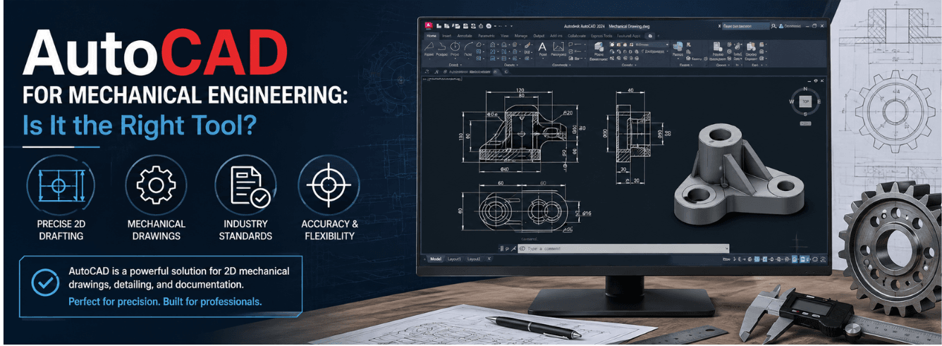
AutoCAD for mechanical engineering remains one of the most widely used combinations in manufacturing and fabrication shops worldwide — but the real question isn’t whether it works, it’s whether you’re tapping into the specialized mechanical toolkit already sitting inside your subscription.
- The AutoCAD Mechanical toolset is included with every standard AutoCAD subscription — it’s not a separate purchase.
- You get 700,000+ standard parts, automatic BOM tables, GD&T symbols, and power dimensioning that plain AutoCAD lacks.
- Mechanical drafting productivity can jump 65% over plain AutoCAD for mechanical-specific tasks, per Autodesk’s own studies.
- At $59 through Zoftis (versus $1,975 direct), a genuine AutoCAD license with the full toolset is accessible for individuals and small shops.
What the Mechanical Toolset Actually Gives You (That Nobody Talks About)
Most articles list the toolset’s features like a brochure. Here’s what matters on the shop floor: the Mechanical toolset rewires AutoCAD’s core drafting engine for how mechanical engineers actually work. It’s not an add-on bolted to the side — it replaces the standard workspace with a purpose-built environment.
Since 2019, Autodesk has bundled this toolset into every standard AutoCAD subscription. If you’ve been running plain AutoCAD for mechanical work, you’ve been drafting with one hand tied behind your back — and the upgrade path costs nothing extra.
The toolset activates when you switch your workspace to “Mechanical” from the gear icon in the bottom-right corner. No separate install, no additional serial number. It’s already there.
What changes when you switch to the Mechanical workspace
- Layer management becomes automatic. The toolset creates and assigns layers based on the object type — dimensions go on AM_DIM, centerlines on AM_CL, hidden lines on AM_HID. You stop managing layers manually.
- Drawing commands get mechanical intelligence. Draw a shaft and the toolset automatically creates centerlines, side views, and section views. Draw a hole and the toolset knows it needs a center mark and diameter callout.
- Parts are parts, not lines. Insert a bolt, bearing, or nut from the library and the toolset treats it as a part object with associated metadata, not a cluster of anonymous geometry.
- Revisions stay tracked. The toolset stamps revision clouds, delta symbols, and revision tables directly onto the drawing border without manual coordinate tracking.
Five Mechanical Drafting Features You’re Probably Missing
Most mechanical engineers using AutoCAD for mechanical engineering stick with the standard profile out of habit. They draw lines, add dimensions manually, and build BOMs in Excel. Here’s what flips when you actually open the toolset.
| Feature | With Mechanical Toolset | Plain AutoCAD |
|---|---|---|
| Power Dimensioning | Single command creates multiple dimensions with automatic spacing, fits, and tolerances based on ISO/ANSI templates | Linear, aligned, and radial dimensions placed individually; tolerance text typed by hand |
| Standard Parts Library | 700,000+ pre-drawn parts — bolts, nuts, washers, pins, bearings, structural steel — inserted as intelligent objects | Draw every fastener from scratch or hunt for third-party block libraries |
| BOM Generation | Auto-generated bill of materials that updates when parts are added, removed, or changed; exports directly to spreadsheet | Manual table creation in paper space; every edit requires retyping |
| Shaft Generator | Enters shaft geometry into a dialog box, toolset draws the shaft, centerlines, and section views simultaneously | Draw centerline, outline, chamfers, keyways, and undercuts as separate linework |
| Spring & Chain Calculators | Built-in calculators for compression, extension, torsion springs and roller chains with automatic drawing generation | Calculate externally, then draft results as static linework |
The power dimensioning feature alone saves enough hours in the first week to justify switching workspaces.
Power dimensioning, explained
In plain AutoCAD, dimensioning a mechanical part is tedious: click the first extension line origin, the second, place the dimension line, repeat. For a part with 30 dimensions, that’s 90 precise clicks — and every one is a chance for misalignment.
Power dimensioning in the Mechanical toolset condenses this. Select the geometry once, pick a reference edge, and the toolset snaps every dimension into place with uniform spacing. It also auto-populates tolerance values from the selected standard (ISO 2768 or ASME Y14.5), so you’re not cross-referencing tables to type ±0.1 into the dimstyle dialog. For mechanical autocad users who produce multiple drawings per day, this is the difference between finishing at 4 PM and finishing at 7 PM.
ISO, ANSI, GD&T: Why Standards Support Makes or Breaks a Mechanical Drawing
A mechanical drawing that doesn’t comply with governing standards isn’t incomplete — it’s legally unbuildable. Shops reject parts over missing datum references and incorrectly called-out tolerances. The Mechanical toolset bakes this compliance into the interface.
Standards baked into the toolset (2026 release)
- ISO: Full support for ISO 128 (technical drawing presentation), ISO 2768 (general tolerances), and ISO 286 (limits and fits)
- ANSI/ASME: ASME Y14.5-2018 GD&T implementation, ASME B18 fastener specs, ANSI surface finish symbols
- DIN & JIS: German DIN standards for European fabrication, Japanese JIS for Asia-Pacific manufacturing
- GB: Chinese national standards for mainland manufacturing supply chains
Set your standard once in the Options dialog (AMOPTIONS), and every dimension, symbol, weld callout, and surface finish mark follows that standard automatically. You can switch standards mid-project without recreating the drawing.
GD&T symbols that actually work
One persistent frustration among mechanical autocad users is the GD&T implementation in plain AutoCAD. You can insert a feature control frame, but it’s just geometry — the software doesn’t understand that a flatness tolerance of 0.05 relates to a specific datum surface. The Mechanical toolset ties GD&T frames to the features they control. Change the datum reference and the frame updates. Move the feature to another sheet and the annotation follows. It’s the difference between a drawing tool and a drafting environment that understands mechanical relationships.
The symbol libraries extend beyond GD&T. Weld symbols with full AWS A2.4 support, surface texture triangles with sampling length and cutoff values embedded, and edge symbols that distinguish between external and internal corners — these aren’t blocks you drag from a folder. They’re parametric objects that resize, reorient, and update their text fields based on context.
AutoCAD vs Inventor vs SolidWorks: Which One for Your Workflow?
This is the question that sits underneath every search for autocad for mechanical engineering. The honest answer depends entirely on what leaves your desk at the end of the day.
| Workflow | AutoCAD (with Mechanical Toolset) | Inventor | SolidWorks |
|---|---|---|---|
| 2D fabrication drawings | Built for this. Standards-compliant, fast, and precise | Possible but indirect — draws from 3D model | Possible but indirect — draws from 3D model |
| 3D parametric modeling | Limited 3D solid modeling; no parametric history tree | Purpose-built parametric CAD with assembly constraints | Industry-leading parametric engine |
| BOM and parts management | Auto-generated from drawing content; spreadsheet export | Full BOM with component properties; ties to Vault | Similar capability through PDM integration |
| Shop floor accessibility | Every machinist and fabricator can open and print DWG files | Requires Inventor or free viewer; extra step to export | Requires SolidWorks or eDrawings; DWG export not always clean |
| FEA and simulation | Not available | Integrated FEA within Inventor Professional | Integrated simulation suite available |
| Learning curve | Moderate — most engineers already know basic AutoCAD | Steep — parametric thinking is a different skillset | Steep — similar parametric learning curve to Inventor |
If your deliverables are 2D drawings that go to a machine shop, AutoCAD with the Mechanical toolset is the most direct path from concept to finished part.
When Inventor makes more sense
If your work involves assemblies of 50+ parts that must interlock and move, and you need interference detection, motion studies, or FEA stress analysis, then Inventor or SolidWorks is the correct choice. Autocad mechanical drafting can document those assemblies beautifully — but it won’t simulate whether the cam follower binds at 3,000 RPM. Many shops run both: Inventor for design and validation, AutoCAD for the final shop drawings that everyone on the floor can read.
The Real Cost of AutoCAD for Mechanical Engineering in 2026
Autodesk sells AutoCAD as a subscription. The list price from Autodesk direct runs approximately $1,975 per year for a single-user license. That price includes the full software, all specialized toolsets (including Mechanical), and access to the current version year plus up to three prior versions.
Through Zoftis, the same genuine license is available at $59 — a 40% reduction from the standard $99 Zoftis rate during promotional periods. It’s the identical product, activated on your own Autodesk account, with the same toolset access and version rights.
| What You’re Paying For | Zoftis Price | Autodesk Direct |
|---|---|---|
| AutoCAD 2026 (2024–2026 version rights) | $59/year | $1,975/year |
| Mechanical toolset (700K+ parts, BOM, GD&T) | Included | Included |
| All 7 specialized toolsets | Included | Included |
| Activation on your own Autodesk account | Yes | Yes |
| Delivery time | 1–12 hours by email | Immediate on purchase |
| Money-back guarantee | 30 days | Limited |
Watch out for “AutoCAD LT for mechanical” recommendations. LT does NOT include the Mechanical toolset, standard parts libraries, or BOM generation. It’s a capable 2D drafting program, but it’s not CAD mechanical software — it’s plain AutoCAD with a lower price tag and stripped features.
Who Should Use AutoCAD for Mechanical Engineering (and Who Shouldn’t)
Let’s be direct. Not every mechanical engineer needs AutoCAD, and some are better served by completely different tools. Here’s how the decision breaks down in practice.
Strong candidates for AutoCAD mechanical drafting
- Fabrication shops producing 2D cut lists, weldment drawings, and assembly instructions for the floor
- Manufacturing engineers who need to document existing parts, create shop aids, and annotate vendor drawings
- Tool and die designers working primarily in 2D with standard component libraries
- Maintenance and facilities engineers who draw layouts, piping runs, and equipment footprints
- Independent mechanical drafters serving multiple clients who all expect DWG deliverables
Better served by 3D parametric CAD
- Product design engineers iterating complex assemblies with dozens of interrelated parts
- Anyone needing FEA, CFD, or motion simulation — AutoCAD can’t do these
- Designers creating renderings or animation for client presentations
- Teams doing top-down design where a change to one part must propagate through the entire assembly
Get AutoCAD with the full Mechanical toolset
Genuine Autodesk AutoCAD for Windows — 2024–2026 release. 1 Year Subscription for $59 (reg $99). Includes the Mechanical toolset with 700,000+ standard parts, BOM generation, and GD&T libraries. Delivered by email in 1–12 hours, activated on your own Autodesk account. 30-day money-back guarantee.
View AutoCAD Pricing →Also available: AutoCAD Commercial License for teams needing named-user seats with full commercial use rights.
Frequently asked questions
Is the AutoCAD Mechanical toolset a separate download?
No. The Mechanical toolset is included with every standard AutoCAD subscription. After installing AutoCAD, switch your workspace to “Mechanical” from the gear icon in the status bar. No separate installer, license key, or activation required.
Can I open mechanical AutoCAD drawings in plain AutoCAD?
Yes — DWG files created in the Mechanical workspace open in any version of AutoCAD. However, intelligent objects like standard parts and BOM tables may display as blocks or proxy objects if the receiving machine doesn’t have the Mechanical toolset loaded. The geometry remains intact and printable; you just lose the parametric intelligence.
Does AutoCAD for mechanical engineering support 3D modeling?
AutoCAD includes 3D solid, surface, and mesh modeling tools, but they are not parametric. You can create 3D parts and assemblies, but unlike Inventor or SolidWorks, there’s no feature history tree. Changing a hole diameter means deleting and recreating the hole feature rather than editing a parameter in a timeline.
What’s the difference between AutoCAD LT and full AutoCAD for mechanical work?
AutoCAD LT is a 2D-only drafting program. It does NOT include the Mechanical toolset, standard parts libraries, BOM generation, GD&T automation, or any of the mechanical-specific features. It also lacks AutoLISP and .NET API support, so you can’t run mechanical automation scripts. For CAD mechanical work, full AutoCAD is the minimum requirement.
Can I get the Mechanical toolset on a Mac?
The Windows version of AutoCAD includes all specialized toolsets, including Mechanical. AutoCAD for Mac does NOT include the Mechanical toolset. If you need mechanical drafting capabilities on a Mac, you’ll need to run AutoCAD for Windows via Boot Camp or a virtualization solution like Parallels Desktop.
How do the standard parts libraries stay current with ISO and ANSI updates?
Autodesk updates the standard parts content with each major release. The 2026 version includes fasteners compliant with the latest ISO 898 (mechanical properties of fasteners) and ASME B18 standards. When you install a new version, the libraries update automatically — you don’t need to download separate content packs.