
Blog
How to Extrude in AutoCAD (Turn 2D Shapes into 3D Solids)

How to Extrude in AutoCAD — Turn 2D Shapes into 3D Solids
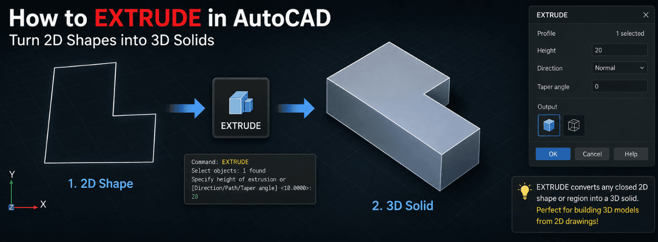
Learning how to extrude in AutoCAD is the single most important step in moving from 2D drafting to 3D modeling. The EXTRUDE command takes a flat shape and gives it depth — turning a rectangle into a box, a circle into a cylinder, or a complex floor plan into a building mass. But EXTRUDE isn’t the only tool: PRESSPULL offers a faster, more intuitive alternative for many situations. This guide covers both commands in full, with real examples, common pitfalls, and pro tips.
- EXTRUDE requires a closed object — a region or a closed polyline. Open shapes create surfaces, not solids.
- PRESSPULL works on closed boundaries, 2D objects, and existing 3D faces — often faster than EXTRUDE for quick edits.
- Taper angles — positive angles taper inward (narrower top), negative angles taper outward (wider top).
- Path extrusion lets you extrude a profile along a curve — ideal for pipes, rails, and trim.
- Always switch to the 3D Modeling workspace and a visual style like Conceptual before starting 3D work.
Before You Start — Set Up Your Workspace
Before you learn how to extrude in AutoCAD, you need the right environment. AutoCAD’s default 2D drafting workspace hides most 3D tools. Here’s how to set up properly.
Switch to the 3D Modeling Workspace
- Click the workspace switching button in the status bar (bottom-right corner) or the Quick Access toolbar.
- Select 3D Modeling from the dropdown menu.
- This loads the 3D-specific toolbars, menus, and palettes.
Tip: You can also type WSCURRENT at the command line and enter 3D Modeling to switch without using the mouse.
Choose a Visual Style
In 2D Wireframe, extruded solids look like messy wire skeletons. Change to a shaded visual style to see what you’re actually building.
- Use the View Controls pulldown menu (top-left of the viewport).
- Select Conceptual or Realistic.
- Try different styles — there’s no wrong answer, and you can change anytime.
Set an Isometric View
Working in Top view makes 3D extrusion confusing. Switch to an isometric view so you can see depth as you extrude.
- Use the View Controls pulldown menu.
- Choose SW Isometric, SE Isometric, NE Isometric, or NW Isometric.
- You can also use the ViewCube in the top-right corner to rotate your view.
The EXTRUDE Command — The Classic Way to Add Depth
The EXTRUDE command is the foundation of how to extrude in AutoCAD. It takes a 2D or 3D curve and extends it to create a 3D solid or surface. Open curves generate surfaces; closed curves generate solids or surfaces.
How to Run the EXTRUDE Command
- Ribbon: Home tab → Modeling panel → Extrude.
- Command line: Type
EXTRUDEorEXTand press Enter. - Menu: Draw → Modeling → Extrude (if Menu Bar is enabled).
Basic EXTRUDE Workflow — Step by Step
- Draw a closed 2D shape — a rectangle, circle, polygon, or any closed polyline.
- Start the EXTRUDE command — type
EXTand press Enter. - Select the object — click the shape and press Enter to confirm selection.
- Specify the height — drag your mouse up or down, then click to set the height, or type a numeric value and press Enter.
- Done — your 2D shape is now a 3D solid.
Note: The extrusion direction follows the Z axis of the UCS that was current when the object was created. If your extrusion goes the wrong way, enter a negative height value.
EXTRUDE Command Options
After selecting objects, you’ll see several options at the command line:
- Mode — choose between Solid (default) or Surface.
- Height — the main extrusion distance (positive or negative).
- Direction — extrude along a specified direction (not just vertical).
- Path — extrude the profile along a selected curve.
- Taper angle — add a draft angle to the extrusion.
- Expression — use a mathematical formula for the height.
| Object type | Can be extruded? | Can be a path? | Notes |
|---|---|---|---|
| Circle | ✅ | ✅ | — |
| Arc | ✅ | ✅ | — |
| Line | ✅ | ✅ | — |
| 2D Polyline | ✅ | ✅ | Crossing segments cannot be extruded |
| Region | ✅ | — | Ideal for extrusion |
| 3D Solid face | ✅ | ✅ | Hold Ctrl to select subobjects |
| Mesh face | — | — | Use MESHEXTRUDE instead |
| Helix | — | ✅ | Can be used as a path |
The Closed-Profile Requirement — Why Some Shapes Won’t Extrude
This is the most common frustration when learning how to extrude in AutoCAD. You draw what looks like a closed shape, run EXTRUDE, and nothing happens — or you get a surface instead of a solid.
Critical: EXTRUDE only creates a solid from a closed object that encloses an area. If your object is not perfectly closed, EXTRUDE creates a surface — not a solid. This is one of the most important concepts in how to extrude in AutoCAD.
What Objects Can Be Extruded as Solids?
- Regions — the safest option. Created with the
REGIONcommand. - Closed polylines — must be perfectly closed with no gaps.
- Circles, ellipses, rectangles — naturally closed.
- Closed splines — can be extruded if they form a closed loop.
How to Fix a Shape That Won’t Extrude
- Try the REGION command — select all lines, arcs, and polylines that form the shape, type
REGION, and press Enter. If the shape can be converted to a region, it will extrude. - Use PEDIT to join lines — type
PEDIT, select one line, choose Join, and select all other lines to merge them into a single polyline. - Check for gaps — use
UNITSto increase precision, then zoom in on corners to find tiny gaps. UseFILLETwith radius 0 to close gaps. - Avoid self-intersecting polylines — polylines that cross over themselves cannot be extruded.
Pro tip: Use the BOUNDARY command to create a region from any closed area. Click inside the closed boundary, and AutoCAD generates a region automatically. This is often faster than tracing or joining lines manually.
Taper Angle — Adding Draft to Your Extrusions
When you extrude in AutoCAD, you’re not stuck with straight, vertical walls. The taper angle option lets you add a draft — essential for parts that need to be removed from molds or for visual effects.
How Taper Angle Works
After selecting objects in the EXTRUDE command, choose the Taper angle option before entering the height. The taper angle must be between -90° and +90°.
| Angle value | Effect | Typical use |
|---|---|---|
| 0° (default) | Vertical walls — no taper | Standard extrusions |
| Positive angle (e.g., 5°) | Top surface is smaller than the base (tapers inward) | Mold draft, casting patterns, plastic parts |
| Negative angle (e.g., -5°) | Top surface is larger than the base (tapers outward) | Funnels,喇叭口, decorative bases |
Warning: If the taper angle is too large or the extrusion height is too long, the object can taper to a point before reaching the full height. AutoCAD won’t warn you — the extrusion simply stops at the point where the walls meet.
Real-World Example: Designing a Molded Part
Imagine designing a plastic housing that needs to be removed from an injection mold. Without a draft angle, the part would stick in the mold.
- Draw the base shape — a rectangle for the housing footprint.
- Run
EXTRUDE, select the rectangle, choose Taper angle, enter 3° (typical for plastic parts). - Enter the height — say 50 units.
- The result is a housing that’s slightly narrower at the top, ready for mold release.
Direction Extrusion — Extruding at an Angle
Sometimes you need to extrude in AutoCAD along a direction that isn’t vertical. The Direction option lets you specify any angle.
When to Use Direction Extrusion
- Slanted supports — angled beams or struts.
- Inclined planes — ramps or sloped surfaces.
- Non-orthogonal geometry — any shape that needs to project at an angle.
How to Use Direction Extrusion
- Start the
EXTRUDEcommand and select your closed object. - Choose the Direction option from the command line.
- Specify two points to define the direction and length of the extrusion.
- The shape extrudes along the line between those two points.
Note: The direction cannot be parallel to the plane of the object being extruded. If you try, AutoCAD will reject the direction.
Path Extrusion — Following a Curve
Path extrusion is one of the most powerful ways to extrude in AutoCAD. Instead of extruding straight up, your profile follows a curved path — perfect for pipes, rails, molding, and decorative trim.
How Path Extrusion Works
The selected path is moved to the centroid of the profile, then the profile is extruded along the path. The extrusion starts from the plane of the object and maintains its orientation relative to the path.
Rules for Path Extrusion
- The path should not lie on the same plane as the object.
- The path should not have areas of high curvature — tight bends can cause the extrusion to fail or distort.
- If the path contains non-tangent segments, AutoCAD extrudes along each segment and miters the joints.
- If the path is closed, the object should lie on the miter plane for the start and end to match up.
Pro tip: Use object snaps to ensure the path starts on or within the contour of the object being extruded. This prevents unexpected offsets.
Path Extrusion vs Sweep — What’s the Difference?
EXTRUDE with a path moves the profile along the path while keeping it oriented to the path. The SWEEP command generally provides more control and better results for complex paths. For simple paths, EXTRUDE works fine. For complex or twisted paths, use SWEEP.
PRESSPULL — The Faster Alternative to EXTRUDE
If you’ve ever used SketchUp, PRESSPULL will feel familiar. It’s an interactive command that lets you click inside a closed area and drag up or down to create a solid. No selecting objects, no typing heights — just click and drag.
How to Use PRESSPULL
- Type
PRESSPULL(orPRES) and press Enter. - Click inside a closed boundary area — you’ll see visual feedback as you move the cursor.
- Drag up to pull a solid out of the area, or drag down to press it into the existing geometry.
- Click to set the height, or type a value and press Enter.
- The command repeats automatically until you press Esc.
What PRESSPULL Can Do
| What you select | What PRESSPULL does |
|---|---|
| Open 2D object (arc, open polyline) | Extrudes to create a surface |
| Closed 2D object (circle, closed polyline) | Extrudes to create a 3D solid |
| Inside a bounded area (click the interior) | Extrudes to create a 3D solid — just like Push/Pull |
| 3D solid face | Offsets the face — expands or compresses the solid |
Keyboard shortcut: In AutoCAD 2010 and higher, press Ctrl+Shift+E to start PRESSPULL instantly.
PRESSPULL for Editing Existing Solids
PRESSPULL isn’t just for creating new solids. You can use it to edit existing 3D objects:
- Select a face of an existing solid and drag — the face moves, extending or shortening the solid.
- Hold Ctrl while clicking a face to offset it, which also affects adjacent faces.
- Use Shift+click to make multiple selections at once.
EXTRUDE vs PRESSPULL — Which One Should You Use?
Both commands let you extrude in AutoCAD, but they excel in different situations. Here’s how to choose.
| Criteria | EXTRUDE | PRESSPULL |
|---|---|---|
| Speed for new shapes | Slower — select object, choose options, enter height | Faster — click inside area, drag |
| Precision | High — type exact numeric values | Lower — drag-based, though you can type values |
| Taper angle | ✅ Full support | ❌ Not supported |
| Path extrusion | ✅ Full support | ❌ Not supported |
| Direction extrusion | ✅ Full support | ❌ Not supported (vertical only) |
| Editing existing solids | Limited — must select faces with Ctrl | Excellent — click face and drag |
| Click-inside-boundary workflow | ❌ Not supported | ✅ Supported — the killer feature |
| Automatic repeat | No — restart each time | Yes — continues until Esc |
Use EXTRUDE when you need taper, paths, or precise numeric control. Use PRESSPULL when you need speed and interactive editing — especially for the click-inside-boundary workflow.
Extruding Text in AutoCAD
Text extrusion is a common need for signage, labels, and 3D logos. Here are three methods to extrude in AutoCAD with text.
Method 1: TXTEXP (Express Tools)
- Type
TXTEXPat the command line (requires Express Tools installed). - Select the text object — it’s exploded into lines and polylines.
- Use
REGIONto convert all closed shapes to regions. - Run
EXTRUDEon the regions.
Drawback: Generates many individual pieces of geometry — editing is difficult.
Method 2: WMF Export/Import (Cleaner Results)
- Create your text in AutoCAD.
- Export the text as a WMF file (
WMFOUT). - Import the WMF back (
WMFIN) — text becomes polylines. - Use
REGIONthenEXTRUDE.
Advantage: Cleaner geometry with fewer artifacts than TXTEXP.
Method 3: Use a Different Font
Some TrueType fonts (like Arial or Times New Roman) work better for extrusion because their outlines are cleaner. Avoid fonts with complex decorative elements unless you’re prepared for cleanup work.
Common EXTRUDE Errors and How to Fix Them
Even experienced users run into problems when they extrude in AutoCAD. Here’s how to troubleshoot the most common issues.
“Cannot extrude selected object”
- Cause: The object is not closed or not a valid region/polyline.
- Fix: Run
REGIONon the object. If that fails, usePEDITto join all segments into a single closed polyline.
Extrusion creates a surface, not a solid
- Cause: The selected object is open (has gaps).
- Fix: Close the shape. Use
PEDITwith the Join option, or redraw withPLINE.
Extrusion goes the wrong direction
- Cause: The UCS Z axis is pointing the wrong way, or you need a negative height.
- Fix: Enter a negative height value. Or use the
UCScommand to realign the Z axis.
Tapered extrusion collapses to a point
- Cause: The taper angle is too steep for the height.
- Fix: Reduce the taper angle or reduce the extrusion height.
Path extrusion fails or looks distorted
- Cause: The path has high curvature or lies on the same plane as the object.
- Fix: Use the
SWEEPcommand instead for better control.
Source objects disappear after extrusion
- Cause: The
DELOBJsystem variable is set to delete source objects. - Fix: Set
DELOBJto 0 (prompt to delete) or 1 (retain source objects).
System variable reference: SURFACEMODELINGMODE controls whether extruded surfaces are NURBS or procedural. DELOBJ controls deletion of source objects. Check both if you’re getting unexpected results.
Frequently asked questions
Why can’t I extrude my shape in AutoCAD?
The most common reason is that your shape isn’t perfectly closed. EXTRUDE only creates solids from closed objects that enclose an area. Try the REGION command — if the shape can become a region, it will extrude. Also check for self-intersecting polylines, which cannot be extruded.
What’s the difference between EXTRUDE and PRESSPULL?
EXTRUDE is the traditional command — you select an object, then specify height, taper, direction, or path. PRESSPULL is interactive — you click inside a closed area or on a face and drag to create or modify geometry. PRESSPULL is faster for quick work but lacks taper angle and path extrusion. EXTRUDE offers more control and precision.
How do I extrude at an angle in AutoCAD?
Use the Direction option in the EXTRUDE command. After selecting your object, choose Direction from the command line, then specify two points to define the extrusion direction and length. The direction cannot be parallel to the plane of the object being extruded.
How do I extrude along a curve in AutoCAD?
Use the Path option in the EXTRUDE command. After selecting your object, choose Path, then select a curve (line, arc, polyline, spline, or helix). The path should not lie on the same plane as the object, and should avoid sharp bends. For complex paths, the SWEEP command often gives better results.
Why is my extrusion a surface instead of a solid?
This happens when the selected object is open (not closed). Open curves create surfaces; closed curves create solids. Check your shape for gaps using PEDIT with the Join option, or convert the shape to a region with REGION.
Can I extrude text in AutoCAD?
Yes. The fastest method is using the Express Tools command TXTEXP, which converts text to polylines — then use REGION and EXTRUDE. For cleaner results, export the text as WMF (WMFOUT) and re-import (WMFIN), then region and extrude. The cleanest approach is to use a font with simple outlines like Arial.
What does the taper angle do in EXTRUDE?
The taper angle adds a draft to your extrusion. A positive angle makes the top smaller than the base (tapers inward). A negative angle makes the top larger than the base (tapers outward). The default is 0° — vertical walls. Taper angles are essential for parts that need to be removed from molds.
How do I measure the volume of an extruded solid?
Use the MASSPROP (Mass Properties) command. Select the solid, type MASSPROP, and press Enter. AutoCAD displays volume, centroid, moments of inertia, and other physical properties of the solid.
Ready to put your AutoCAD skills to work?
Get a genuine Autodesk AutoCAD for Windows license — 2024–2026 release, 1 Year Subscription, 30 Days Refund. Delivered within 1–12 hours.
Get AutoCAD Now — From $59Also available: AutoCAD Commercial License · AutoCAD LT 2027