
Blog
How to Do Cut and Fill Calculations in AutoCAD (and When You Need Civil 3D)

How to Do Cut and Fill Calculations in AutoCAD (and When You Need Civil
3D)
How to Do Cut and Fill Calculations in AutoCAD (and When You Need Civil 3D)
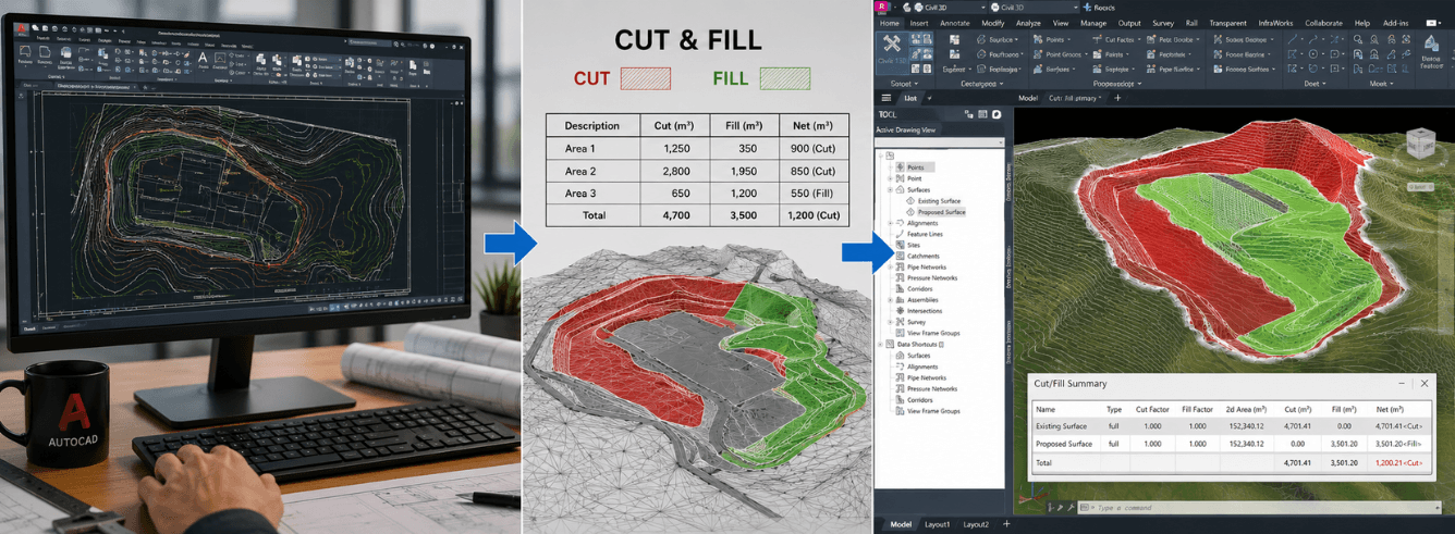
Knowing how to do cut and fill calculations in AutoCAD is essential for site planning, but the honest answer is that base AutoCAD only approximates earthwork volumes. For accurate, project-ready numbers, you need Civil 3D.
Why base AutoCAD falls short for earthwork
Let’s be straight: you can do cut and fill calculations in base AutoCAD, but you probably shouldn’t for real projects. Here’s what you’re up against with vanilla AutoCAD.
Surface creation without dedicated tools
Base AutoCAD can create 3D surfaces from contours or points, but there’s no dedicated surface workspace. You’re manually building TIN surfaces using generic 3D tools that weren’t built for volume analysis.
- No Volume Dashboard: There’s no built-in surface comparison tool. You need to manually calculate differences between existing and proposed grade surfaces.
- Manual cross-section drafting: You draw sections one by one, measure areas with polylines, and calculate volumes by hand or in Excel.
- Prone to error: Each manual step introduces potential mistakes — missed contours, inaccurate area measurements, calculation errors.
The most common workflow in base AutoCAD is: draw cross-sections, use LIST or AREA commands, export to Excel, and apply the average end area formula. This works for small sites but becomes impractical for large projects.
What happens when you do earthwork in base AutoCAD
A study comparing conventional methods (AutoCAD + Excel) against Civil 3D’s BIM approach found small deviations under 5%. But that small deviation hides a big difference in efficiency and reliability. The conventional method produced volumes of 5,715 m³ cut and 111,196 m³ fill, while Civil 3D’s Volume Dashboard produced 5,665 m³ cut and 112,038 m³ fill — close numbers, but Civil 3D delivered them automatically with better traceability and less than 1% deviation.
Base AutoCAD can get you close. Civil 3D gets you accurate, auditable, and defendable — without the manual grind.
How Civil 3D does cut and fill calculations natively
Civil 3D has purpose-built tools for earthwork. Here’s how the workflow works, independent of any third-party plugins, directly from Autodesk’s own documentation.
Step 1: Create your existing ground surface
Import survey data, contour lines (DXF, SHP, or KML), or point clouds. Use Toolspace → Prospector → Surfaces → right-click → Create Surface. Name it appropriately — “Existing Ground” is common.
Step 2: Build your proposed design surface
This can come from:
- Grading objects created with Civil 3D’s grading tools
- Feature lines representing design elevations
- Corridor surfaces from road or site design
- Imported design contours from KML, LandXML, or other formats
Pro tip: Use grading groups to organize your proposed surfaces. Civil 3D’s grading tools let you create finished ground surfaces by applying grading criteria to footprints — and once you create a grading group surface, volume tools automatically calculate cut and fill requirements.
Step 3: Calculate volumes with the Volume Dashboard
Go to the Analyze tab and select Volume Dashboard. Click Create New Volume Surface and set:
- Name: e.g., “Cut Fill Volume”
- Surface Type: TIN Volume Surface
- Base Surface: Existing Ground
- Comparison Surface: Proposed Design
The Volume Dashboard shows cut volumes in red, fill in green, and a net graph. For visualization, right-click the surface, open Surface Properties, go to Analysis, set ranges to two, and assign red for cut, green for fill.
Step 4: Generate the cut and fill report
From the Volume Dashboard, select Generate Cut/Fill Report. You’ll get total cut volume, total fill volume, and net earthwork balance.
Critical: Civil 3D allows you to apply cut and fill factors (also called bulking and compaction factors). For example, a cut factor of 1.2 means material expands 20% when excavated. A fill factor of 1.075 (derived from 1/0.93) accounts for 7% compaction. Set these to 1.0 for raw volume, but adjust for real-world material handling.
Step 5: Cross-section method for linear projects
For roads, pipelines, or any linear earthwork, use the Compute Materials command.
- Create an alignment along the project centerline
- Generate sample lines at regular intervals (Home → Sample Line)
- Create multiple section views
- Use Analyze → Compute Materials to run the volume calculation
- Generate section-by-section volume reports
This approach is essential for linear projects where volumes vary significantly along the length.
| Capability | AutoCAD Civil 3D | Base AutoCAD |
|---|---|---|
| Volume Dashboard | ✓ Built-in, automatic | ✗ Manual or custom LISP |
| Compute Materials (section-based) | ✓ Full toolset | ✗ Manual cross-section drafting |
| Grading volume tools | ✓ Auto-balance, incremental adjust | ✗ Trial and error |
| Method choice: Average End Area / Prismoidal / Composite | ✓ Three methods available | ✗ Only Average End Area by hand |
| Cut/fill factors (bulking/compaction) | ✓ Built-in | ✗ Manual adjustment in Excel |
| Visualization (cut/fill maps) | ✓ Automatic color mapping | ✗ Manual hatch/solid creation |
| Audit trail / pay item reporting | ✓ QTO Manager, pay item links | ✗ No automated reporting |
| Workflow efficiency | ~10-30 minutes for a typical site | ~Several hours to days |
Average end area vs prismoidal vs composite methods
Civil 3D gives you a choice of three volume calculation methods for sectional analysis. Choosing the right one matters for accuracy.
Average end area method
The classic approach: volume = (Area₁ + Area₂)/2 × distance between sections. Use this when cut/fill areas between successive stations are similar in shape. It’s fast but less accurate when terrain changes dramatically between sections.
Prismoidal method
Similar to average end area but uses an additional cross-section at the midpoint between stations. More accurate when terrain has greater changes between stations.
Composite method
Civil 3D creates polygons between sample lines and computes bounded volumes using the actual surface data — no interpolation formulas. This method is limited to two-surface comparisons (cannot include corridor shapes) but is the most accurate when surface triangles are smaller than the sample line interval.
Pro tip: For most site grading projects, the Composite method delivers the best balance of accuracy and automation. Reserve Prismoidal for projects with highly irregular terrain where the extra accuracy justifies the computational cost.
Balancing cut and fill volumes automatically
One of Civil 3D’s most powerful features is the ability to automatically balance cut and fill volumes — something base AutoCAD can’t do at all.
Balancing means adjusting proposed grade elevations so that the volume of material cut equals the volume of material required for fill. This reduces material import/export costs and is a fundamental part of site design.
How to balance using grading volume tools
After creating a grading group (a collection of grading objects), use the Grading Volume Tools:
- Click the Grading Volume Tools button from the grading creation toolbar
- Accept a grading group — the volume is automatically calculated
- Use the automatic balancing button to set the required volume to zero
- Civil 3D incrementally raises or lowers the grading group until the net volume is as close to zero as possible
Advanced application: You can even balance across multiple site elements — for example, use a pond to absorb the excess cut from a road design. Create separate volume surfaces for each element, then adjust the pond volume to match the road cut volume using the grading volume tools.
Base AutoCAD requires manual elevation adjustments and re-calculating everything from scratch each time. Civil 3D does it automatically, showing the history of adjustments and allowing you to target specific net volumes.
Common troubleshooting issues and fixes
Even with Civil 3D, things can go wrong. Here are the most common issues and how to fix them.
Problem: Volume Dashboard returns blank or zero volumes
Likely cause: Coordinate system units are set to degrees (or another angular unit) rather than meters or feet. Civil 3D can’t compute volumes in angular units.
Fix: Check your drawing units (Drawing Settings → Units and Zone). Ensure linear units are set to a valid length unit.
Problem: Volume reports fail on older Civil 3D versions
Likely cause: A known issue with Volume Dashboard’s Generate Cut/Fill Report function in Civil 3D 2019–2022. Microsoft hotfixes exist for some versions.
Fix: Try exporting to LandXML and re-importing, or use the Compute Materials workflow for sectional reports instead.
Problem: Different methods give different results
Explanation: This is expected. Volume Surface (Volume Dashboard) and Compute Materials (section-based) will always differ mathematically. A study found deviations under 5% between methods, which is considered acceptable for earthwork estimation. Use the method that best matches your project type.
Critical: You can include multiple corridor baselines in a volume calculation, but ensure the shapes of all sampled corridors are formed accurately. Misformed corridor shapes will produce unreliable volumes.
Ready to do earthwork the right way?
AutoCAD Civil 3D for Windows — genuine Autodesk license, 1-year subscription from $79, includes full AutoCAD, delivered to your own Autodesk account within 1–12 hours, backed by a 30-day money-back guarantee.
Get Civil 3D now →Frequently asked questions
Can I do cut and fill calculations in base AutoCAD?
You can do approximate calculations by manually creating surfaces, drawing cross-sections, and calculating areas with the AREA command, then exporting to Excel. However, this is slow, error-prone, and impractical for projects beyond a few acres. Civil 3D automates the entire workflow with purpose-built volume tools.
How to do cut and fill calculations in AutoCAD Civil 3D?
Create an existing ground surface and a proposed design surface. Then use the Volume Dashboard (Analyze tab) to create a TIN Volume Surface comparing the two. Civil 3D automatically calculates cut and fill volumes and can generate a report. For linear projects, use the Compute Materials command with sample lines.
What is the difference between Volume Dashboard and Compute Materials?
Volume Dashboard calculates cut and fill volumes by comparing two TIN surfaces using the Composite method. Compute Materials calculates volumes along an alignment using sample lines and lets you choose between Average End Area, Prismoidal, or Composite methods. Volume Dashboard is better for site grading; Compute Materials is better for roads, pipelines, and other linear projects.
How do I balance cut and fill volumes in Civil 3D?
Use the Grading Volume Tools. After creating a grading group, open the Grading Volume Tools dialog, view the net volume, and click the auto-balance button to set the required volume to zero. Civil 3D automatically adjusts the grading elevation to achieve the target volume. You can also balance across multiple site elements by targeting a specific net volume for one element to offset another.
Do different Civil 3D volume methods give different results?
Yes — and that’s expected. Volume Dashboard (Composite method) and Compute Materials (Average End Area or Prismoidal) will produce different numbers. A study found deviations of about 3% between methods, which is considered acceptable for earthwork estimation. Choose the method that matches your project type and reporting requirements.
What are cut and fill factors in Civil 3D?
Cut and fill factors (also called bulking and compaction factors) adjust volumes for real-world material behavior. A cut factor >1.0 accounts for material expansion (swell) when excavated. A fill factor >1.0 accounts for compaction (shrinkage) when material is placed as fill. For example, a fill factor of 1.075 (derived from 1/0.93) accounts for 7% compaction of material.