
Blog
How to Make a Block in AutoCAD (Static and Dynamic)

How to Make a Block in AutoCAD (Static and Dynamic)
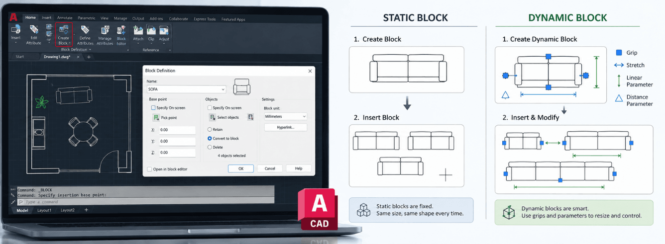
Learning how to make a block in AutoCAD is one of the most valuable productivity skills you can pick up — and this guide walks you through both static blocks and dynamic blocks, from first click to finished library component.
- Three ways to create a static block: BLOCK command, WBLOCK, and the Convert to Block option — each has a different use case.
- Layer 0 and ByBlock properties determine how your block behaves when inserted — get this right and you’ll avoid colour and linetype headaches.
- Dynamic blocks use visibility states, parameters, and actions to give you multiple configurations in a single block definition.
- AutoCAD 2026 introduced BSEARCH (formerly BCONVERT) — an AI-powered tool that finds identical geometry and converts it to blocks automatically.
Static block creation: the BLOCK command
Creating a block in AutoCAD starts with the BLOCK command. This groups selected objects into a single named entity that you can reuse throughout your current drawing.
The Block Definition dialog box has three critical sections you need to fill:
Name your block
Every block needs a unique name. AutoCAD allows up to 255 characters, including hyphens, underscores, and dollar signs — but keeping names short and descriptive makes insertion faster.
Set the base point
The base point is where your block attaches to your cursor when inserting. Choose it carefully — a door block’s base point should be at the hinge, not the middle of the panel. Use object snaps to pick a specific point, or type X,Y,Z coordinates directly.
Select the objects
Click “Select Objects” and use any selection method to pick what goes into your block. The dialog shows the count of selected objects so you can verify nothing was missed.
Three options control what happens to your original objects: Convert to Block turns them into an instance of the new block; Retain keeps them as separate objects; Delete removes them entirely.
Once defined, a block is stored in the drawing’s block table. Every time you insert it, AutoCAD creates a block reference — an instance that points back to that original definition. This is what keeps file sizes small: one definition, dozens or hundreds of references.
Blocks have a superpower: edit the definition once, and every reference updates automatically. Need to change a symbol across 50 drawings? Redefine the block and it propagates.
WBLOCK: Save a block to its own drawing file
WBLOCK (Write Block) creates a separate DWG file from selected objects or an existing block definition. While the BLOCK command keeps blocks inside your current drawing, WBLOCK exports them to your file system — ready to insert into any other drawing.
Three source options for WBLOCK
The Write Block dialog box gives you three choices for what to export:
- Block — pick an existing block definition from the drop-down list. This saves the block as a standalone DWG file.
- Entire drawing — exports everything in model space as a separate drawing file.
- Objects — select specific geometry that doesn’t need to be a block first. This creates a new drawing file from your selection.
WBLOCK also has a hidden “Convert to Block” option. If you select Objects and check “Convert to Block”, it creates a block definition inside your current drawing and saves it as a DWG file. This is a two-for-one productivity move.
Once saved as a DWG, your block becomes part of your personal block library. Use the INSERT command (or drag and drop) to bring it into any drawing. Unlike the BLOCK command — which only stores the definition inside one file — WBLOCK makes your blocks portable.
| Feature | BLOCK command | WBLOCK |
|---|---|---|
| Stored in current drawing only | ✓ | — |
| Saved as external DWG file | — | ✓ |
| Insertable into other drawings | — | ✓ |
| Creates block definition without saving a file | ✓ | — |
| Can export non-block geometry directly | — | ✓ |
How to insert a block into your drawing
AutoCAD gives you multiple ways to insert blocks — the Blocks palette, the ribbon gallery, Tool Palettes, and DesignCenter. Each tool serves a slightly different workflow.
The Blocks palette (recommended)
Type INSERT or click the Insert icon on the Home tab. The Blocks palette opens with four tabs: Current Drawing, Recent, Favorites, and Libraries.
- Current Drawing — blocks defined in your active file.
- Recent — blocks you’ve used recently across any drawing.
- Favorites — blocks you’ve marked with a star for quick access.
- Libraries — browse any folder of DWG files or a specific DWG file that contains blocks.
When you select a block, AutoCAD prompts you for the insertion point, scale (X and Y independently), and rotation angle. You can specify these in the dialog box or type them at the command line for more control.
For blocks from your WBLOCK library, use the Libraries tab in the Blocks palette. Navigate to the folder containing your saved DWG files and drag any block into your drawing — no separate INSERT command needed.
Block properties, Layer 0, and ByBlock explained
How a block behaves when inserted depends entirely on the layer and colour properties you set before creating it. Get this right and your blocks adapt to any layer. Get it wrong and you’ll spend time fixing colour and linetype mismatches.
Option 1: Objects on Layer 0 with ByLayer properties
This is the recommended approach. Draw your block geometry on Layer 0 with colour, linetype, and lineweight set to ByLayer. When inserted, the block takes on the colour and linetype of the layer it’s placed on. This gives you maximum flexibility — one block definition that works on any layer.
Option 2: Objects on Layer 0 with ByBlock properties
Set object properties to ByBlock instead of ByLayer. When inserted, the block takes on whatever colour, linetype, or lineweight you assign to the block itself through the Properties palette. This is useful when you want to control appearance at the block level rather than the layer level — for example, forcing a centreline to always be red regardless of the insertion layer.
Option 3: Objects on a specific layer with explicit properties
Draw geometry on a layer other than Layer 0, with explicit colours and linetypes. The block will always display those exact properties, ignoring the layer it’s inserted on. Use this sparingly — it can cause confusion and reduces the block’s reusability.
Layer 0 is the key. The most flexible and least confusing approach is to draw all block geometry on Layer 0 with ByLayer properties. The block then takes the properties of the layer you insert it onto — exactly what most users expect.
Dynamic block basics: visibility states
A dynamic block lets one block definition contain multiple configurations. Need a door that shows closed, open 45°, open 90°? That’s one dynamic block instead of five separate blocks.
Creating a block with visibility states
Visibility states are the simplest way to make a dynamic block. Here’s the workflow using a real example — a door with multiple swing angles:
- Draw all configurations in the same drawing. In the door example, draw the closed door, then the 45°, 60°, and 90° open versions. Position each so they share the same insertion point (the hinge).
- Create a regular block containing all the geometry. Name it “Door – Dynamic” and select every object.
- Open the Block Editor (double-click the block). On the Block Authoring Palette, add a Visibility Parameter and place its icon near the block.
- In the Visibility States dialog, rename the default state to “Closed,” then create additional states: “Open 45,” “Open 60,” “Open 90.”
- For each state, use the Visibility panel to hide objects that don’t belong. In the “Closed” state, hide all the open-door geometry. In “Open 45,” hide everything except the 45° configuration.
- Save the block and test it in your drawing — clicking the visibility icon brings up a dropdown list of configurations.
Visibility states don’t just reduce the number of blocks in your library — they also make insertion faster. Instead of searching through a long block list for “door closed,” “door 45,” and “door 90,” you insert one block and pick the state from a dropdown.
Use the WBLOCK command to save your dynamic block as a separate DWG file once it’s working. This adds it to your library for use in any future project.
Parameters and actions: stretch, rotate, and scale
Visibility states are just the beginning. The Block Editor’s Parameters and Actions give you even more control — stretch a block to fit, rotate it dynamically, or scale it while keeping certain geometry fixed.
Linear parameter with stretch action
This is the most common parameter-action combination. Add a Linear Parameter to your block (in the Block Editor), then add a Stretch Action linked to it. When you insert the block, dragging the grip stretches the geometry. Used for adjustable shelves, variable-length beams, or any component with a dimension that changes per use.
Rotation parameter
Add a Rotation Parameter to give your block an adjustable rotation grip. Unlike the standard ROTATE command, this stays within the block — you can rotate part of the block while the rest stays fixed. Think of a hydraulic cylinder with a rotating piston.
Parameter manager for exact control
For precise geometry changes, the Parameter Manager lets you create user parameters and link them to dimensional constraints. This is more advanced — you’re essentially building a parametric model inside your block. Insert the block and change dimensions in the Properties palette, exactly like adjusting a standard object.
All dynamic block functionality lives in the Block Editor. Access it by double-clicking any block and selecting “OK” in the Edit Block Definition dialog, or type BEDIT at the command line. The Block Authoring Palette gives you all the Parameters and Actions you need.
Smart Blocks in AutoCAD 2026: BSEARCH
AutoCAD 2026 introduced Smart Blocks: Search and Convert (BSEARCH) — an AI-powered tool that finds identical geometry and converts it to blocks automatically.
BSEARCH replaced BCONVERT (deprecated in 2026) and now supports text variations too. Select one instance of geometry, run BSEARCH, and AutoCAD finds every identical match in your drawing. You review the matches, confirm the selection, and convert them all to a single block definition in one operation.
The 2026 update added text detection — the tool now finds matching MTEXT or regular text objects and can convert them into block attributes, making it even more powerful for repetitive labelling tasks.
BSEARCH is a huge time-saver for cleaning up drawings from consultants or clients. Instead of manually finding and replacing 50 instances of a symbol, let BSEARCH find them all and convert them in a few clicks.
Ready to start using blocks in AutoCAD?
Get a genuine Autodesk AutoCAD license for Windows — 2024–2026 release. 1 Year Subscription, delivered within 1–12 hours with a 30-day money-back guarantee.
Check AutoCAD Price →Also available: AutoCAD for Mac
Frequently asked questions
How to make a block in AutoCAD with WBLOCK?
Type WBLOCK (or W) at the command line. In the Write Block dialog, choose your source: Block (pick an existing block), Entire drawing, or Objects (select new geometry). For creating a reusable block from current objects, choose Objects, set a base point, select the objects, and enter a filename and path. The objects are saved as a DWG file you can insert into any drawing.
What is the difference between BLOCK and WBLOCK?
BLOCK creates a block definition stored inside your current drawing only — it cannot be inserted into other drawings. WBLOCK writes the block (or selected objects) to an external DWG file, which can be inserted into any drawing using the INSERT command. Use BLOCK for local reusability, WBLOCK for building a block library.
How to create a dynamic block in AutoCAD with visibility states?
Draw all configurations in one file, then create a regular block containing all geometry. Double-click to open the Block Editor, add a Visibility Parameter from the Block Authoring Palette, and create visibility states for each configuration. Use the Visibility panel to hide geometry that doesn’t belong in each state. Save and test.
What is the best practice for creating block geometry on Layer 0?
Draw block objects on Layer 0 with colour and linetype set to ByLayer. When the block is inserted, it inherits the properties of the layer it’s placed on. This gives maximum flexibility and avoids colour/linetype conflicts. For elements you want to control separately, use ByBlock instead of explicit colours.
What is BSEARCH in AutoCAD 2026?
BSEARCH (formerly BCONVERT) is AutoCAD 2026’s Smart Blocks: Search and Convert tool. Select one instance of geometry, run BSEARCH, and AutoCAD finds all identical matches in your drawing. You review the matches and convert them all to a block in one operation. The 2026 version also finds text variations for conversion to block attributes.