
Blog
How to Flatten 3D to 2D in AutoCAD (FLATTEN Command Guide)

How to Flatten 3D to 2D in AutoCAD (FLATTEN Command Guide)
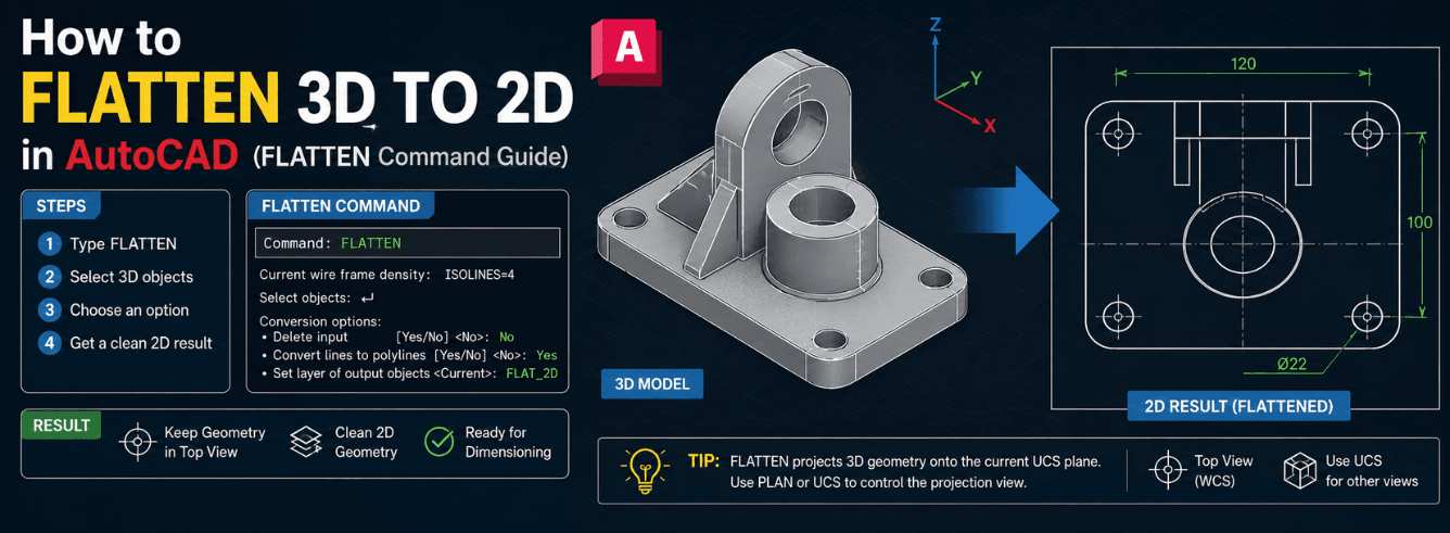
If you need to autocad flatten 3d to 2d, you’ve probably discovered that the process isn’t as straightforward as it sounds. Whether you’re working with a client’s 3D model, cleaning up imported geometry, or preparing fabrication drawings, knowing how to flatten 3D to 2D in AutoCAD correctly saves hours of frustration and rework.
- FLATTEN is fastest but destructive — it modifies geometry in place and can break blocks.
- FLATSHOT produces the best hidden-line output for 3D solids but creates a static block.
- Viewport projection in a layout view is non-destructive and updates with model changes.
- The right method depends on whether you need a clean 2D drawing, a visual reference, or an editable line work export.
- Always run an AUDIT or PURGE after flattening to remove leftover 3D data and empty layers.
Why flattening goes wrong more often than you think
Most people assume flattening means hitting a button and watching everything drop to Z=0. The reality is messier. A drawing that looks flat can still carry Z values, invisible 3D solids, or proxy objects that refuse to cooperate. When you set out to autocad flatten 3d to 2d, you’re dealing with data that doesn’t always behave the way it appears on screen.
The core issue: AutoCAD stores elevation data even when it renders as a flat line. A line drawn at Z=5 looks identical to one at Z=0 in plan view. But the moment you dimension, hatch, or export to DWG output, the phantom Z values create gaps, missing intersections, and hatch boundaries that simply don’t close.
A drawing that looks flat isn’t necessarily flat — and that distinction costs real hours on fabrication drawings.
What flattening actually does
Flattening converts geometry with varying Z values into truly 2D objects at elevation zero. When you autocad flatten 3d to 2d properly, you’re creating geometry that other software can read without errors. This matters for:
- Creating 2D projection views from 3D models for documentation
- Preparing line work for export to other CAD or CNC software
- Fixing imported geometry with stray elevation data
- Making blocks and xrefs behave when overlaid with planar geometry
- Producing clean drawings for fabrication or permitting
Flattening does not create a true orthographic projection from every angle. FLATTEN only projects to the current UCS plane. If you need top, front, and side views from a 3D model, use FLATSHOT or viewport projection instead.
Method 1: The FLATTEN command, step by step
The autocad flatten command is the most direct approach when you need to autocad flatten 3d to 2d, but it comes from Express Tools, so it isn’t always loaded. If you type FLATTEN and get “Unknown command,” you need to install or load Express Tools first.
How to run FLATTEN correctly
- Type FLATTEN at the command line and press Enter.
- Select the objects you want to flatten, or press Enter to select everything.
- When prompted “Remove hidden lines?”, choose Yes for a cleaner 2D projection, No to keep all line work.
- Wait for the command to process — complex 3D solids can take a while.
- Check that objects now sit at Z=0 using the Properties palette (select any object, check its Z value).
FLATTEN is destructive. It explodes blocks, converts 3D solids to exploded line segments or regions, and permanently modifies geometry. Never run it on your only copy of a drawing. Save a backup first.
When FLATTEN makes sense
FLATTEN shines when you’re cleaning up 2D geometry that has picked up stray elevation values. Think imported survey data, drawings from other software, or files that have been through multiple coordinate systems. It’s also useful for quick flattening of a small number of objects when you don’t need hidden-line treatment.
What it isn’t good at: producing clean hidden-line views of 3D solids. The exploded result is usually a mess of triangle segments, and the “remove hidden lines” option doesn’t work reliably on complex geometry. For that, you need FLATSHOT.
Express Tools availability note
FLATTEN is an Express Tool, meaning it’s included with full AutoCAD but not with AutoCAD LT in older releases. AutoCAD LT 2024 and later include FLATSHOT but not FLATTEN. If you’re on LT and need to autocad flatten 3d to 2d, Method 2 or 3 is your path.
Method 2: FLATSHOT for proper hidden-line projection
FLATSHOT is the professional tool for converting 3D models to 2D drawing views. When you need to autocad flatten 3d to 2d from actual solid geometry, this is the command that produces clean, usable results. Unlike FLATTEN, it works by projecting 3D solids onto the current plane and generating a block that contains visible lines, hidden lines, and tangent edges as separate elements.
Running FLATSHOT correctly
- Switch to a view that shows the angle you want to project (Top, Front, Left, or a custom 3D orientation).
- Type FLATSHOT and press Enter.
- The FLATSHOT dialog box opens. Choose “Insert as new block” or “Replace existing block.”
- Set the foreground line color and linetype — this controls visible edges.
- Set the obscured line color and linetype — this controls hidden lines behind the object.
- Click Create, then place the block in your drawing.
Set your visual style to 2D Wireframe before running FLATSHOT. If you’re in a shaded or realistic visual style, the projection can capture edge artifacts you don’t want in your 2D output.
What you get with FLATSHOT
The output is a block containing pure 2D line work — no 3D geometry, no surfaces, no solids. This makes it ideal for DWG output that other software can read, for creating CNC-ready paths, or for building a 2D documentation set from a 3D model. The hidden lines are generated automatically, so you get an orthographic projection that respects the 3D model’s actual geometry.
The limitation: FLATSHOT only works with 3D solids and surfaces. Meshes, regions, and plain line work won’t project properly. Also, the result is a snapshot — if you change the 3D model, you have to re-run FLATSHOT to update the 2D view.
FLATSHOT in AutoCAD LT
AutoCAD LT 2024 and later include FLATSHOT. If you’re on LT 2023 or earlier, this tool isn’t available, and you’d need full AutoCAD or a different workflow. Zoftis offers full AutoCAD for Windows at a significant discount to list, which includes FLATSHOT, FLATTEN, and the rest of Express Tools.
Method 3: Viewport projection without touching your model
If you need to autocad flatten 3d to 2d for documentation purposes without modifying the 3D geometry at all, viewport projection in a layout view is the cleanest option. This keeps your model intact while presenting a flattened, hidden-line view on paper space.
Setting up a projected viewport
- Switch to a layout tab — Layout1 or any you’ve created.
- Create a viewport if one doesn’t already exist (type MVIEW or use the layout wizard).
- Double-click inside the viewport to activate it.
- Use the ViewCube or type VIEW to set the projection direction — Top, Front, Left, or a custom angle.
- Type VISUALSTYLES and choose “Hidden” or “2D Wireframe” for a clean projected look.
- Double-click outside the viewport to exit model space. The view now shows a 2D projection without altering geometry.
This method is non-destructive. The 3D model stays exactly where it is, with all its solids, surfaces, and properties intact. The 2D projection is purely visual, controlled by the viewport. If you edit the model later, the projection updates automatically.
What viewport projection can and can’t do
| Capability | Viewport Projection | FLATTEN / FLATSHOT |
|---|---|---|
| Non-destructive to 3D model | Yes — model stays intact | No — geometry modified or replaced |
| Creates actual 2D line work | No — visual projection only | Yes — true 2D entities |
| Updates with model changes | Automatically | Manual re-run required |
| Exportable to other CAD software | Limited — only via PDF or plot | Full DWG with 2D entities |
| Hidden line treatment | Yes — via visual styles | FLATSHOT yes, FLATTEN unreliable |
Viewport projection is excellent for documentation, presentations, and plotting. It’s the wrong tool when you need actual 2D line work for CNC programming, laser cutting, or export to software that doesn’t understand AutoCAD viewports.
The three methods compared for AutoCAD Flatten 3D to 2D
When you need to autocad flatten 3d to 2d, choosing the right method makes all the difference. Here’s the honest breakdown of when each approach wins:
| Scenario | Best Method | Why |
|---|---|---|
| Quick cleanup of stray Z values in 2D geometry | FLATTEN | Fast, works on lines and polylines, no setup |
| Creating a 2D drawing from a 3D solid | FLATSHOT | Proper hidden-line projection, clean block output |
| Documentation views that must update with model changes | Viewport projection | Non-destructive, automatic updates |
| Exporting 2D line work to other software | FLATSHOT | True 2D entities, no viewport dependencies |
| Flattening a whole drawing with blocks and xrefs | FLATTEN (with caution) | Only tool that handles all object types |
| AutoCAD LT 2023 or earlier user needing projection | Viewport projection | FLATSHOT and FLATTEN unavailable |
If you regularly need to autocad flatten 3d to 2d, FLATSHOT is the workhorse. FLATTEN is a cleanup tool. Viewport projection is for documentation. Using the right tool for the task saves more time than any single command ever will.
Common flattening problems and how to fix them
Problem 1: FLATTEN explodes blocks and destroys attributes
This is the most common complaint when people try to autocad flatten 3d to 2d using FLATTEN. The command doesn’t just set Z=0 — it explodes blocks and converts dynamic block properties into static geometry. Attributes become text objects. Dynamic grips disappear.
Fix: Before flattening, use BURST (Express Tool) to convert attributes to text while keeping block geometry intact. Or isolate the blocks you need to keep and flatten only the rest. Better yet, use FLATSHOT for 3D solids and leave 2D blocks alone.
Problem 2: Objects at Z=0 still won’t hatch or dimension properly
Some geometry appears flat but carries invisible 3D data from proxy objects, regions, or surfaces. The Z=0 check in Properties says zero, but the object still behaves as if it has elevation.
Fix: Run AUDIT to find and fix invalid objects, then PURGE to remove unused 3D styles and proxy data. If the problem persists, copy the geometry to a new drawing using COPYBASE at 0,0,0 and paste into a fresh file.
Problem 3: FLATSHOT creates a block but the hidden lines are wrong
This usually means the visual style or the projection plane isn’t set correctly. FLATSHOT projects to the current UCS plane. If your UCS is rotated or tilted, the projection will be off.
Fix: Type UCS and then WORLD to reset to the world coordinate system. Set your view direction explicitly using the ViewCube or VIEW command. Then re-run FLATSHOT.
Problem 4: The flattened drawing still has 3D visual styles active
You flattened everything, but switching visual styles still shows shaded geometry. That’s because flattening doesn’t remove visual style data from the drawing — it just modifies the geometry.
Fix: Type VISUALSTYLES and set the current style to 2D Wireframe. Then run PURGE to remove unused 3D visual styles from the drawing database.
Problem 5: Imported 3D files have wireframe geometry that won’t flatten
STEP, IGES, or STL imports often contain wireframe edges, meshes, and surfaces mixed together. FLATTEN chokes on these, and FLATSHOT ignores non-solid geometry.
Fix: Use CONVTOSOLID on closed meshes or surfaces to convert them to 3D solids first. Then run FLATSHOT. For wireframe line work, use PROPERTIES to manually set Z=0 on selected objects, or use the Quick Select tool to grab everything and force elevation to zero.
Choosing the right tool for your situation
Here’s a practical decision flow based on what you’re actually trying to accomplish when you autocad flatten 3d to 2d:
Scenario: You need a fabrication drawing from a client’s 3D model
Use FLATSHOT. Generate top, front, and side projections as separate blocks. Place them in a layout view with dimensions. Export as PDF or DWG. This gives the fabricator clean 2D line work without any 3D complexity.
Scenario: You imported a survey file and nothing sits flat
Use FLATTEN, but save a backup first. Select all, flatten, remove hidden lines. Then run AUDIT and PURGE. Check that text, dimensions, and leaders survived. Expect some block explosion and be ready to fix attribute loss.
Scenario: You want presentation views that update as the design evolves
Use viewport projection in layout view. Set up one viewport per projection direction. Apply Hidden or Conceptual visual styles. When the model changes, the views update automatically. This is the non-destructive workflow that keeps your 3D model intact.
Scenario: You need to export 2D line work to a CNC or laser cutting program
Use FLATSHOT and then explode the resulting block. This gives you pure 2D entities — lines, arcs, circles — at Z=0. Export as DXF or DWG to your cutting software. The clean 2D line work imports without any 3D artifacts.
Frequently asked questions about AutoCAD Flatten 3D to 2D
Does the FLATTEN command work in AutoCAD LT?
No. FLATTEN is an Express Tool, and Express Tools are not included with AutoCAD LT in any version. AutoCAD LT 2024 and later do include FLATSHOT, which covers most projection needs. Full AutoCAD includes both FLATTEN and FLATSHOT.
How do I load Express Tools if FLATTEN isn’t available?
In full AutoCAD, you can reinstall or enable Express Tools from the Autodesk installer. On Windows, go to Control Panel → Programs → Uninstall/Change → Autodesk AutoCAD → Add or Remove Features, and check the Express Tools option. On Mac, Express Tools are not available at all — use FLATSHOT or viewport projection instead.
What’s the difference between FLATTEN and setting Z=0 in Properties?
Setting Z=0 in Properties only changes the elevation of selected objects. It doesn’t project 3D solids, doesn’t handle hidden lines, and doesn’t work on objects with multiple Z values. FLATTEN actively projects geometry to the UCS plane and gives you the option to remove hidden lines.
Can I flatten a drawing that contains xrefs when I need to autocad flatten 3d to 2d?
FLATTEN does not work directly on xrefs. You need to either bind the xref first (XBIND or INSERT), then flatten the bound geometry. Or open the xref file separately, flatten it, save, and reload. FLATSHOT also doesn’t project xref geometry unless you bind it first.
Why does my flattened drawing still show 3D objects in shaded view?
Flattening modifies geometry but doesn’t remove 3D visual style data or purge 3D-related objects from the drawing. Switch your visual style to 2D Wireframe, then run AUDIT and PURGE to clean up. If shaded objects remain, they may be proxy objects or regions that FLATTEN didn’t process — convert them to solids first and re-flatten.
Is there a way to flatten 3D to 2D in AutoCAD without losing block information?
Yes. Use FLATSHOT for 3D solids — it preserves the output as an organized block with visible and hidden line layers. For 2D geometry with Z elevation issues, select objects individually and change Z to 0 in Properties rather than running FLATTEN. This keeps blocks and attributes intact.
Need AutoCAD to put these flattening techniques to work?
Genuine Autodesk AutoCAD for Windows — 2024–2026 release. One-year subscription at $59 (regularly $99). Delivered by email in 1–12 hours, activated on your own Autodesk account, backed by a 30-day money-back guarantee.
Get AutoCAD for $59 →Or see our full commercial license options for teams.